High Performance Windows
Thermal and optical performance of residential and commercial windows
Strengthening a Building's "Skin"
Building envelopes play a crucial role in the energy balance of buildings, imposing an annual 15.5 quad (quadrillion Btus) primary energy expenditure today (at a cost of $155 Billion) and a further penalty on peak space conditioning loads that must be offset by expensive HVAC systems and on peak electric loads that place a strain on the electric grid.
The long term transformative vision of this program aims to convert the overall building envelope (transparent and opaque elements) from today's net energy cost of 15.5 quads to ultimately become a net energy supply to the building. This is accomplished by:
- Dynamically managing thermal flows daily and seasonally, via optical properties, conductivity and thermal storage
- Utilizing and controlling daylight to offset electric lighting
- Generating and/or storing electrical and thermal energy, respectively, in building envelope elements
- Reducing uncontrolled air leakage through the building envelope and by employing innovative envelope elements to capture and manage air exchange, thus offsetting mechanical ventilation
Just as human skin is an all-important barrier and thermal regulator of the human body, the building "skin", as envisioned here, is the first critical element in defining goals for building energy performance and comfort.
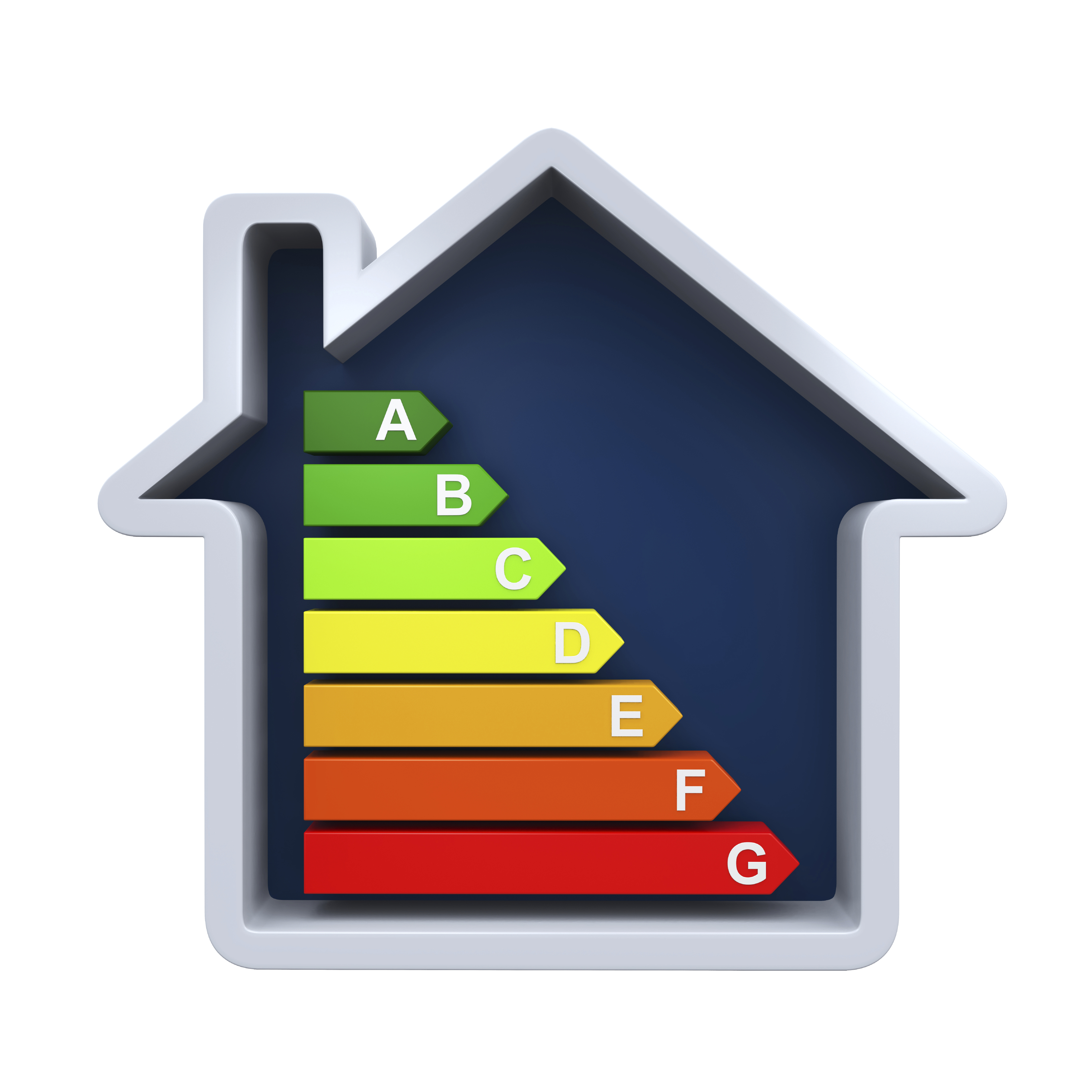
The most efficient HVAC or lighting system is the one that does not have to work at all because the envelope has neutralized or captured the thermal load at the building skin and provided required interior illumination. These high-performance energy functions can be implemented while also providing view, security, thermal comfort, privacy, and aesthetic solutions demanded of building owners, thereby enhancing the economic attractiveness of these solutions and accelerating widespread market adoption. Windows though are often the lowest thermally performing component of the building envelope.
Berkeley Lab's Windows and Envelope Materials Group program is intended to address the highest priority elements of the vision outlined above. It addresses the most pressing technical and market barriers that impede achievement of this stretch vision for the building envelope.
Related Technologies
 Vacuum Insulated Glazing (VIG)
Evacuated glazing units (EGU) or vacuum insulating glazing (VIG) are an emerging technology developed as a concept some 20-30 years ago, but only now approaching wide-spread commercialization and acceptance. EGU is therefore an active and rapidly changing area of research. EGU for residential and commercial use is a promising technology capable of meeting the rigorous thermal performance requirements of net-zero energy windows. While some EGU technology has been available in Japan and other markets as early as 1996, it has achieved minimal market penetration in the U.S. because insulating performance of currently manufactured units R = 4.7 h·°F·ft2/BTU (0.83 m2·K/W) is not greater than some high performance double pane insulating glazing system, design features restrict use in very hot and cold environments, and relatively high costs. New EGU products are being developed, claiming insulating performance up to R = 14 h·°F·ft2/BTU (2.5 m2·K/W), far better than standard triple glazing, as well as the ability to be installed in all U.S. climate regions.
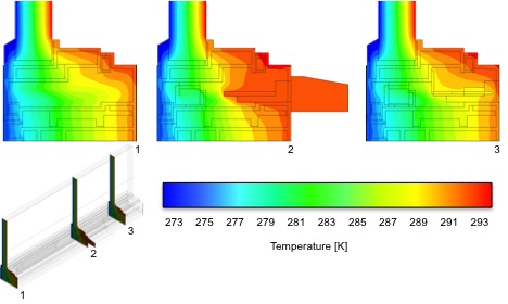
The COG thermal performance of VIG has been studied in previous work, primarily at the University of Sydney. They have developed the process for evaluation of total heat flow by analytical methods that have been adapted and implemented into the WINDOW and THERM 7 software.

Thermal Conductance Of The Evacuated Glazing
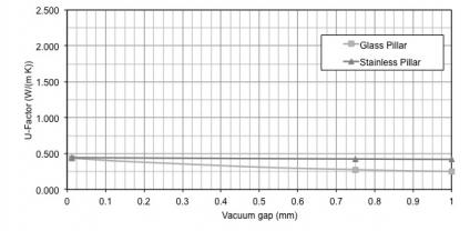
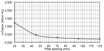
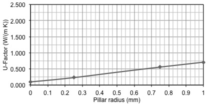
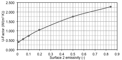
Thermal Conductance of the space in EGU is the sum of the conductance of the low pressure gas (air), radiation conductance, and pillar array. Conductance of low pressure gasses is calculated using formula by Corruccini. Glass pane in EGU are separated by an array of small support elements. Typically, these support elements have the cylindrical shape and are often referred to as "pillars". Typical geometry of the pillar is 0.5-1.0 mm diameter and 0.05 mm (50 mm) height. They are typically spaced 25-50 mm apart in a form of square or staggered matrix. Conductance of these elements can be measured or numerically modeled to determine accurate thermal performance. Approximate method also exists and is based on the combination of modeling and analytical work for the conduction through small cylinders in contact with infinite parallel plates with thickness much larger than cylinder height.
Relevant Publications
Hart, R.H.; and Curcija, D.C. 2013. "Modeling of Vacuum Insulating Glazing." Proceedings of the Thermal Performance of Building Envelopes XII, Clearwater Beach, Fl. December, 2013
Collins, R.E.; and Robinson, S.J. 1991. "Evacuated Glazing". Solar Energy. Vol. 47, No. 1, pp. 27-38.
Collins, R.E.; Fischer-Cripps, A.C. 1991. "Design of Support Pillar Arrays in Flat Evacuated Windows." Aust. J. Phys.
Corruccini, R.J. 1959. Gaseous Heat Conduction at Low Pressures and Temperatures". Vacuum. Vol. 7-8, pp.19-29
Jelle, B.P., A. Hynd, A. Gustavsen, D. Arasteh, H. Goudey, R. Hart. 2012. "Fenestration of today and tomorrow: A state-of-the-art review and future research opportunities". Solar Energy Materials and Solar Cells, Vol. 96, pp 1-28.
Simko, T.M. 1996. Heat Transfer Processes and Stresses in Vacuum Glazing. PhD thesis, The University of Sydney.
Facilities
Thermal Properties Laboratory
Quantitative IR Thermography
Thermal Conductivity Apparatus
Mobile Windows Thermal Test (MoWiTT) Facility
 Current window technology is focused on meeting ENERGY STAR criteria (U ~0.30, SHGC <0.30) and is commonly achieved by double glazed windows with an argon gas fill and a single low-e coating. Increasing the insulating (R) value of windows, while dynamically optimizing solar gain, has the long-term potential to eliminate this energy drain. The ideal residential window will have very low heat loss year round, collect passive solar energy in the winter and reject solar gain in summer, while allowing daylight and view as desired. The technology proposed in this project will result in windows with wide range of SHGCs (0.18 – 0.45). The windows will have onboard intelligence to determine the optimal SHGC by varying the shading position.
We aim to create a flexible technology platform for cost effective, high performance residential windows that maximizes net useful solar gain in heating mode and minimizes solar gain in cooling mode. Fully automated operation to optimize energy savings is provided by an intelligent, networkable, sensor/microprocessor package that is easily installed and calibrated. The windows are designed to minimize annual energy use in cold and mixed climates (i.e. Minneapolis and Washington DC). About twenty-five windows will be fabricated and installed in a cold climate houses to demonstrate both peak load reduction and annual heating and cooling energy reduction. The windows will be able to function autonomously and in a networked configuration. In a networked configuration they will communicate with each other. We are also working with code officials, utilities, and industry stakeholders to ensure proper credit of smart dynamic windows in future code cycles.
Performance Critera For Residential Zero Energy Windows
In this project we define the properties necessary for windows to have zero impact on the energy use in a typical house (i.e. a Zero Energy Window). Highly insulating window development efforts often focus on the development of an insulating glass unit with center-of-glass U-factors of 0.10 Btu/hr-ft2-F (0.57 W/m2-K), a target which can be achieved with three layers of glass, two low-e coatings and a low-conductivity gas fill. Vacuum units and aerogel are other alternatives under R&D. Spacer and frame effects can be expected to degrade this performance; as such a total window U-factor of 0.12 Btu/hr-ft2-F (0.68 W/m2-K) is targeted as being a realistic long-term product for ZEHs.
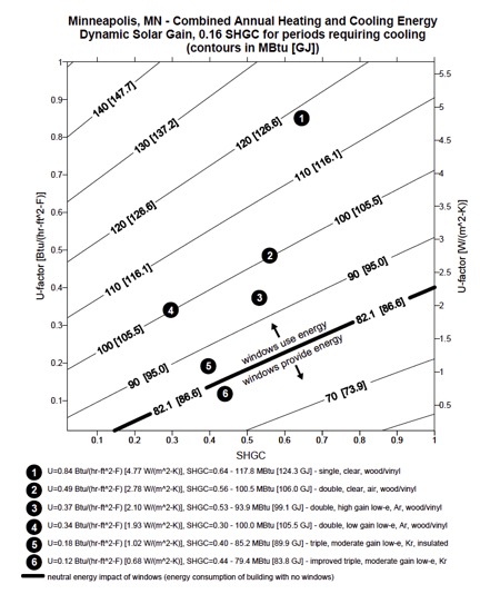
While there is clear data from prior studies that lower U-factor windows are needed for ZEHs throughout the central and northern US, the question of an optimal SHGC, particularly in climates with some cooling load, deserves significant attention. As such, our analysis focuses on looking at the impacts of a typical window's SHGC as well as on the potentials from windows with dynamic SHGC (i.e. a SHGC which is reduced in the summer). This SHGC reduction can come from the use of a mechanized shading device or from an active glazing (i.e. an electrochromic glass). A summer SHGC of 0.16 was picked as representative of a window with a reduced summer SHGC; such a value allows for the design of a window that can offer a reasonable view (visible transmittance of glass greater than 0.30) but will make a serious reduction in solar gains.
For zero-energy homes to become a reality, it is desirable that windows provide a net source of energy, to the extent that this is practical in various climates. Admitting solar heat gain during the heating season to reduce the need for furnace operation is the only means for improving upon the energy consumption calculated for the baseline windowless house. However, the solar gains associated with the windows during the cooling season must not outweigh the energy saved on heating and the thermal conductance of the windows must be low enough to reduce the thermal losses to less than the solar gains. Daylight admitted through windows minimally reduces the consumption of energy for lighting but is not considered here since most residential lighting needs are at night and this effect is minor.
In a city with large heating loads (Ex. Minneapolis) it is clear that products typical of today's Energy Star level (#3,#4) are far from the zero energy use line. A product that represents today's best available technology (#5) (which exceeds the Energy Star standards) is significantly closer to the zero energy use line, but not quite there. Improving on this window's U-factor significantly, such as window #6, brings this product nearly to the zero energy use line. Dynamic windows offer the potential for the windows to transmit solar radiation when it is useful (the heating season) and to minimize solar transmission during the cooling season—potentially becoming energy gainers (Arasteh 2006).
Automated Control
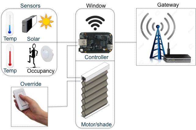
To take full advantage of dynamic windows an automated shade algorithm is developed. Fully automated operation to optimize energy savings in the context of other market drivers is provided by an intelligent, networkable, sensor/microprocessor package that is easily installed and calibrated. The control algorithm can be implemented inside the window or on a home automation microprocessor. It only requires a few input values from local sensors integrated in the window to determine the optimal shading operation.
Four sensing types are integrated into the window; Motion sensor, exterior temperature, interior temperature, and solar radiation heat gain. The intent of the motion sensor is to determine when an occupant is home, or near the window, and therefore remain in a manual override state if placed into one. The remaining three sensors are utilized to determine the direction of net heat flow through the window. With knowledge of the heat flow, we develop a control algorithm to put the shade into the most energy efficient position.
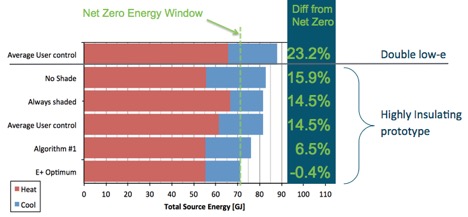
The algorithm incorporates changes in shade state relative to the heating, Theat, and cooling, Tcool, thermostat set points. Assumptions regarding the set points are made for day and night. These values can be adjusted for specific installations. If the thermostat state (heating/cooling/idle) is available to the algorithm directly, then these are taken from the actual set points. The time when interior temperature is between the thermostat set points represents time when energy is not being used to maintain home temperature. Therefore, the shade state algorithm should be designed to maximize time spent in this zone. Several different control options were considered in order to extend the time between set points. The net heat flow method is implemented in the prototype unit (Algoritym #1 in figure). The net heat flow through the glazing is determined with the simple equation:
q = Uwindow * (Text – Tin) + SHG
Where Uwindow is a property of the window itself, which varies depending on the shade state. Text, and Tin are read from the integrated window sensors. SHG is the product of SHGC and incident radiation. Because SHGC is highly dependent on solar incident angle we instead measure total solar gain through the system. This net heat flow equation is very useful because it directly looks at the conditions local to the window, and evaluates how to optimize the local net heat flow (Firląg 2015).
Sensor accuracy was tested extensively in the field. One major out come of this testing was the development of a solar sensor to more accurately represent actual solar intensity. The steps taken to determine the accuracy of the BW solar sensor are outlined in Dussault 2015.
Validation Testing
In order to understand user response to the system, and how it is operated in the real world, we have identified several homeowners to participate in a demonstration project. Participants were selected from a pool of volunteers who have recently purchased Pella Designer series windows with Insynctive technology. Additional considerations include typical climate of home location, exterior conditions such as shading from neighboring houses, orientation, and quantity of windows in the home.
As part of the study, several windows in a participant's home are temporarily retrofitted (for the duration of the study) with an automated shading system and associated sensors and controls. Sensors will include window mounted interior and exterior temperature readings, solar intensity, and an occupancy sensor. The windows will wirelessly transmit the position of the shade (open/closed) to a dedicated router in the home that will transmit this information to the researchers via cellular connection. All experimental data will be recorded anonymously. At the completion of the study participants will be asked to complete a short survey regarding their experience with the system. The survey responses will be used to inform researches on user acceptance, potential design modifications, and market for the technology. The automated shading system and associated components will be removed from participant homes and windows will be returned to their original state before the project is concluded.
Moving Dynamic Windows Into the Residential Market
A key functional characteristic of the automated window is that its thermal/solar optical properties can change over a wide range to manage energy and comfort. The project team is addressing numerous design and technical issues related to how users can benefit from this "smart product", both in a stand-alone mode as well as part of home automation systems. However, the potential market impact also depends on how other decision makers interpret and accept these performance potentials: building codes and standards, voluntary rating programs like Energy Star or LEED, utility rebate programs, etc.
We live in a world that is largely defined by static properties of products that are easily measureable, e.g. a maximum .3 SHGC (as specified by NFRC) is needed by a window to meet a building code, but modeling and field tests show that a window whose SHGC can vary from .15 to .40 will have lower energy use in summer and winter than the window with fixed properties.
How do we give appropriate annual energy credit for such a product? How sensitive are energy savings to control sequences? Can the control actions be "guaranteed"? Can a smart window have even more value for demand response and peak load management? What happens when the controls are overridden? How sensitive are these questions to climate and orientation? How does an inspector verify the required properties? What risks are there for all the stakeholders?
To address these and related issues we have formed an Advisory Committee to help address market readiness issues such as code compliance, performance rating, connection with home automation systems and feasibility for builders to incorporate "smart windows" in their plans. The committee will initially focus on the needs of this DOE/LBNL/Pella Smart Window project but will be broad enough in scope to support other existing ( e.g. electrochromic glass) and future DOE smart window efforts. Note that DOE is funding a new effort with the Attachment Energy Rating Council to "rate" the performance of dynamic window systems. The AERC will use new tools developed by LBNL for this purpose but ratings wont be available for several years.
Relevant Publications
Dariush Arasteh, Howdy Goudey, Yu Joe Huang, Christian Kohler, and Robin Mitchell. "Performance Criteria for Residential Zero Energy Windows." In 2007 ASHRAE Winter Meeting. Dallas, TX, 2006.
Szymon Firląg, Mehrangiz Yazdanian, Charlie Curcija, Christian Kohler, Simon Vidanovic, Robert Hart, Stephen Czarnecki, "Control algorithms for dynamic windows for residential buildings," Energy and Buildings, Volume 109, 15 December 2015, Pages 157-173.
Jean-Michel Dussault, Christian Kohler, Howdy Goudey, Robert Hart, Louis Gosselin, Stephen E. Selkowitz, "Development and assessment of a low cost sensor for solar heat flux measurements in buildings," Solar Energy, Volume 122, December 2015, Pages 795-803.
Facilities
Thermal Properties Laboratory
Full-scale Testbeds
Quantitative IR Thermography
Mobile Windows Thermal Test (MoWiTT) Facility
Field Measurements
Materials Characterization
The U.S. window market today represents a remarkable transformation to products that use about 50% of the energy that was typical of early 1980s products, but windows still account for ~4 Q of energy use at an annual cost of $40B. The technology to convert windows to net energy neutral products exists in prototypes and niche market products but is not available in volume at competitive prices.
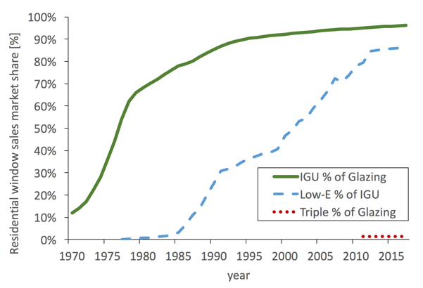
Low-e shows a rapid rise in market penetration, while triple-pane market
share is stagnant at around 1.4 percent.
Production and product integration issues have discouraged the use of traditional 3-pane insulating glass units (IGU) in residential windows. Thus, new highly insulating glazings that do not require changes in current frame designs, can be mass produced at affordable cost, and enable the thermal performance benefits of 3-pane glazings are desired.
We outline here a DOE-industry partnership with a goal to capture the ~2Q of heating energy lost by windows. The partnership involves a technology push component based on refinement and market introduction of a novel, highly insulating “thin triple” glass product that can be incorporated into almost any existing window frame and can be fabricated at modest added cost.
A companion market pull program engages a wide range of traditional market transformation actors and programs to build the demand that will encourage industry investment in the new designs. Two window manufacturers and four component suppliers are engaged, as are a number of utilities, energy efficiency organizations, and government entities with the goal of reaching mainstream markets in the next two years.
Technology
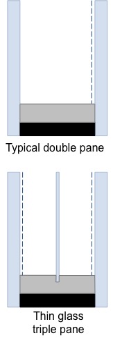
This highly insulating glazing project focuses on the development of alternative center glazing layers for multiple low-e/gas-filled units. Our aim is to increase the number of technological options available to industry for center glazing layers. The two options in use today, suspended films and triple glazed glass units with low-emissivity coatings and/or insulating gas fills, are technologies that have been in use for over two decades. Using lightweight, thin, non-structural layers, the focus of this project, offers several potential manufacturing and performance advantages:
- A single piece spacer is possible reducing labor and material costs, and potential for gas fill leakage.
- No significant weight changes over industry standard double-pane units, thus minimal or no changes in standard operating hardware
- Thinner center layer allows products to fit in existing cross-sections, reducing the need for revised framing systems.
- Pressure equalization between the internal gaps is possible, reducing potential glass deflection.
The concept of the “drop-in replacement” IGU simplifies adoption of the new technology but at some sacrifice in performance. We explore in this project how use of existing frames will constrain overall performance. Center-of-glass performance much better than that obtained by thin-triple-pane IGU designs will not result in much whole window performance improvement without further enhancements to typical frames.
LBNL's prior efforts to understand the thermal performance potentials of various design options culminated with the writing of a report on this subject titled in "Highly Insulating Glazing Systems using Non-Structural Center Glazing Layers". We showed that non-structural center layers that do not create a hermetic seal at the edge have the potential to be as thermally efficient as standard designs while potentially eliminating some of the production and product integration issues that have discouraged the use of triples. Thus, flexibility exists in how a center layer can be inserted into an IG unit without compromising thermal performance. Several IR experiments on un-insulated and insulated edge cases pointed out the importance of edge insulation in minimizing edge deflection. Understanding the impacts of deflection in standard and non-standard three layer units is important both to highly insulating window development and ratings and labeling efforts.
Performance and cost
Modeled and tested IGUs incorporating non-structural thin glass center layers have been shown to perform on par thermally with traditional methods of 3-pane glazing construction. The majority of the market today is made up of 2P-lowe. These units have one low-E coating inside the IGU. The “2P-surf4” option adds a second low-E to the inner
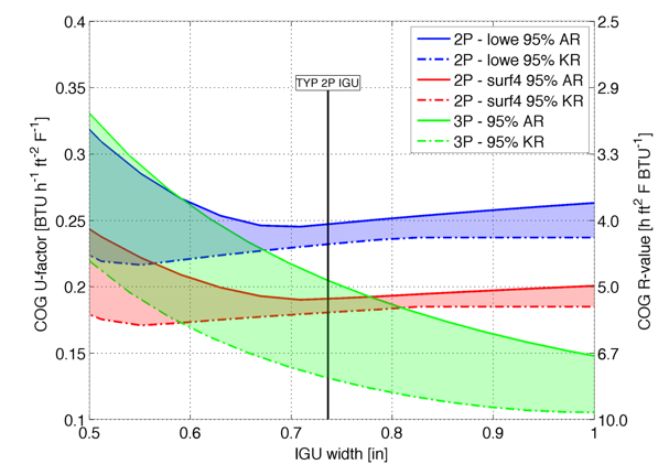
gas fill. The performance ranges obtainable by double-pane low-e
(2P-lowe), double-pane low-e with roomside low-e (2P-surf4), and
thin-glass triple-pane low-e (3P) are shown. 3mm glass is used
everywhere but center-pane of triple where 0.7mm glass is used.
glazing on the room facing surface to provide modest additional insulating value. It is clear that manufacturers optimize the IGU width for double-pane with 95% Argon gas fill – the most commonly constructed IGU currently on the market. It is also clear from the data that a triple glazed unit with narrow gas spaces must switch from Argon to Krypton to provide the large, desired increase in R value, from R5 to almost R8.
“Cost effectiveness” and “paybacks” are often the first questions asked for new efficiency options. We have estimated the incremental manufacturing costs of various improvements to window thermal performance using several common IGU designs. Glass, coatings, gas fill, and the assembly (including spacers) costs were each itemized. Since 2012, when we first examined this concept, material costs have dropped dramatically. Glass cost has dropped from nearly $5/sf to less than $1/sf. Argon fill costs have remained nearly negligible and Krypton fill costs have fallen to around $0.50 per liter with waste of 3 percent.
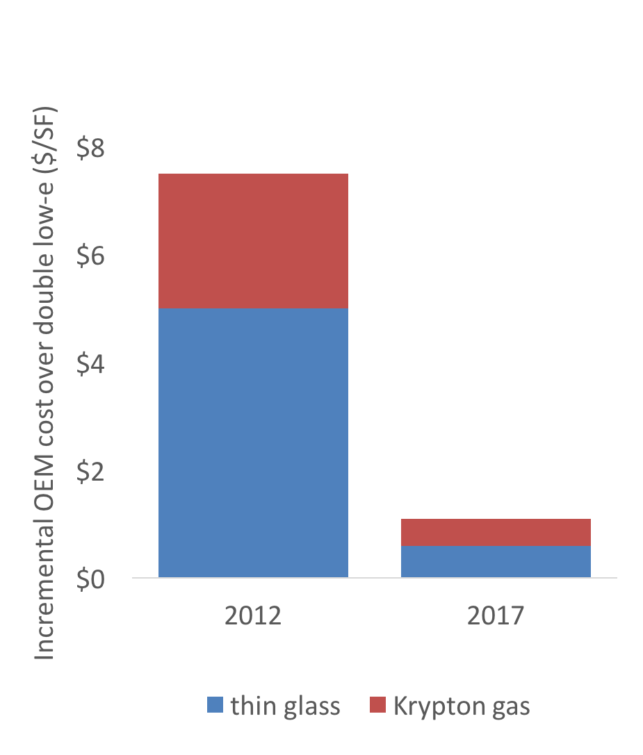
material costs over double-pane low-e
glazing. Costs have dropped sharply in
the last few years.
There are several potential challenges that need to be addressed before thin glass can be brought to market, including a business case for the new technology, material cost, manufacturability, durability and dedicated spacer development. LBNL works with glass and window manufacturers by providing design assistance, product testing, and thermal modeling as part of the development effort.
The designs proposed in this project build on proven approaches to insulating glass manufacturing. By using technologies that are currently available from several vendors, this project reduces the business and market risk. Proven heat transfer reduction techniques are the foundation for the variations being researched. In principle our approach can be implemented without major investments in production facilities, by using existing materials that are combined and assembled in novel ways.
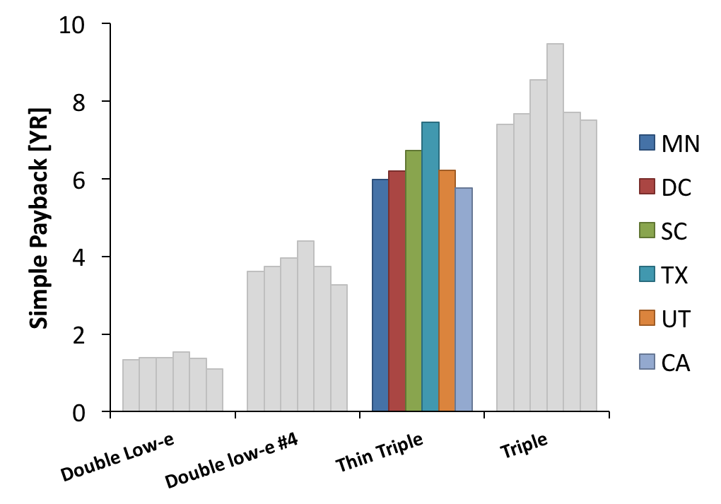
incremental cost estimates. MN: Minneapolis; DC: Washington DC;
SC: Charleston; TX: Houston; UT: Salt Lake City; CA: Los Angeles.
2P-lowe: double glazed, low-e; 2P-surf4: double low-e with extra
low-e on room facing surface; 3P-tg: triple, thin glass; 3P-opt:
triple standard glazing, larger spacing
Relevant Publications
Hart, R., Selkowitz, S. & Curcija, C. "Thermal performance and potential annual energy impact of retrofit thin-glass triple-pane glazing in US residential buildings." Build. Simul. (2019) 12: 79. https://doi.org/10.1007/s12273-018-0491-3
Selkowitz, S., R. Hart, and C. Curcija. "Breaking the 20 Year Logjam to Better Insulating Windows." Proceedings of the 2018 ACEEE Summer Study on Energy Efficiency in Buildings, August 2018, Pacific Grove, CA.
Van Den Bergh, Sofie, Robert Hart, Bjørn Petter Jelle, and Arlid Gustavsen. "Window Spacers and Edge Seals in Insulating Glass Units: A State-of-the-Art Review and Future Perspectives." Energy and Buildings 58 (2013) 263–280. LBNL-6122E.
Jelle, Bjørn Petter, Andrew Hynd, Arlid Gustavsen, Dariush K Arasteh, Howdy Goudey, and Robert Hart. "Fenestration of Today and Tomorrow: A State-of-the-Art Review and Future Research Opportunities." Solar Energy Materials and Solar Cells 96 (2011) 1-28. LBNL-5304E.
Gustavsen, Arlid, Steinar Grynning, Dariush K Arasteh, Bjørn Petter Jelle, and Howdy Goudey. "Key Elements of and Materials Performance Targets for Highly Insulating Window Frames." Energy and Buildings 43.10 (2011) 2583-2594. LBNL-5099E.
Gustavsen, Arlid, Goce Talev, Dariush K Arasteh, Howdy Goudey, Christian Kohler, Sivert Uvsløkk, and Bjørn Petter Jelle. "Experimental and Numerical Examination of the Thermal Transmittance of High Performance Window Frames." Thermal Performance of the Exterior Envelopes of Whole Buildings XI International Conference, December 5-9, 2010. Clearwater Beach, FL, 2010. LBNL-3886E.
Arasteh, Dariush K, Howdy Goudey, and Christian Kohler. "Highly Insulating Glazing Systems using Non-Structural Center Glazing Layers." 2008 Annual ASHRAE Meeting. Salt Lake City, UT, 2008. LBNL-611E.
Arasteh, Dariush K, Dragan C Curcija, Yu Joe Huang, Charlie Huizenga, and Christian Kohler. "Evaluating Fenestration Products for Zero-Energy Buildings: Issues for Discussion." SimBuild 2006: Building Sustainability and Performance Through Simulation. Cambridge, MA, 2006. LBNL-61249.
Arasteh, Dariush K, Howdy Goudey, Yu Joe Huang, Christian Kohler, and Robin Mitchell. "Performance Criteria for Residential Zero Energy Windows." 2007 ASHRAE Winter Meeting. Dallas, TX, 2006. LBNL-59190.
Apte, Joshua S, and Dariush K Arasteh. Window-Related Energy Consumption in the US Residential and Commercial Building Stock. 2006. LBNL-60146.
Arasteh, Dariush K, Stephen E Selkowitz, and John R Wolfe. "The Design and Testing of a Highly Insulating Glazing System for Use with Conventional Window Systems." Journal of Solar Energy Engineering 111.1 (1989) 44-53. LBL-24903 Revised.
Selkowitz, Stephen E. et al., United States Statutory Invention Registration No. H975, entitled "Thermal Insulated Glazing Unit", published Nov. 5, 1991
Related Links:
Efficient Windows Collaborative: Unbiased information on the benefits of energy-efficient windows
Principal Investigator(s)
Team Members
Facilities
Thermal Properties Laboratory
Quantitative IR Thermography
This study examines the thermal performance impact of center-of-glass (COG) deflections in double- and triple-pane insulating glass units (IGUs) installed at several locations throughout the US. Deflection was measured during summer and winter temperatures; the results show that outdoor temperature variations can be represented a linear change in COG gap width in double- and triple-pane IGUs within the temperature ranges measured. However, the summer-winter temperature-induced deflection is similar in magnitude to the observed spread in COG deflection of similar units at the same temperature, which suggests that factors other than temperature are of equal importance in determining the in-situ deflection of windows. The effect of deflection on thermal performance depends on the IGU's designed gap. Units constructed with smaller-than-optimal gaps often exhibit significant U-factor change due to temperature-induced reduction in gap width. This effect is particularly problematic in high-performance triple glazing where small gap dimension changes can have a large impact on performance.
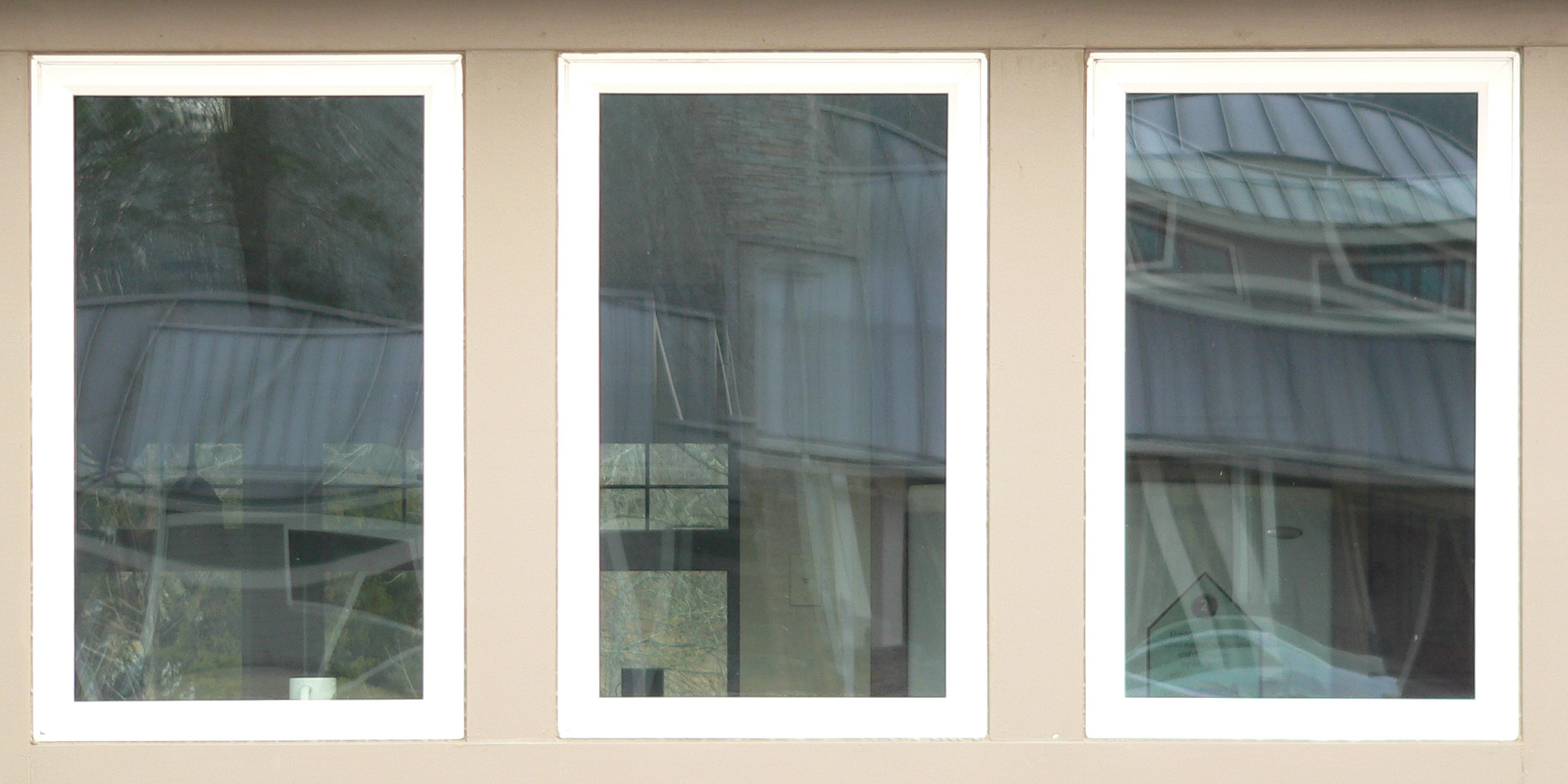
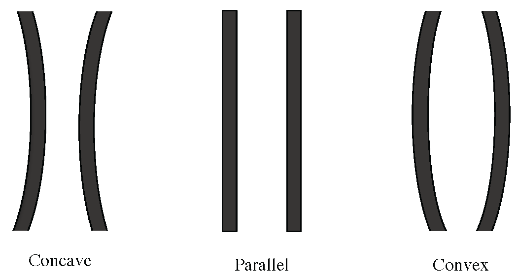
COG deflection, i.e., the difference in gas space width at the COG compared to the edge-of-glass (EOG), as illustrated in Figure 1, can result from several factors; initial manufacturing conditions that establish a bias toward either concave or convex deflection depending on the relative elevation or atmospheric pressure at the manufacturing facility compared to at that installation location; gas fill temperature offset experienced during fabrication compared to average gas temperature during typical use; dissimilar diffusion rates of gases into or out of gas-filled IGUs over time; and transient natural environmental conditions including temperature, pressure, and wind load, which might induce temporary, reversible deflection.
An industry standard addresses the initial COG deflection of a unit while it is still in the manufacturing facility where it was produced [3], but there are currently no requirements or guidelines on acceptable deflection of installed IGUs. Insulating performance of windows in the U.S. is simulated and validated using the procedures outlined in National Fenestration Council (NFRC) technical documents 100 and 102, respectively. For highly insulating windows, in this paper defined as windows with thermal performance better than U=1.7 watts per square meter per kelvin (W/m2K), an acceptable validation test per NFRC 100 can vary by up to 0.17 W/m2K from the simulations. On the most insulating products currently certified (0.51 W/m2K), this translates to a 33 percent allowable variation. Therefore, validation testing of highly insulating windows might not recognize potential cold temperature thermal degradation.
Along with reduced insulating performance, COG deflection can concentrate solar energy reflected off the glass surface. These solar reflections have reportedly caused permanent distortion on vinyl siding and damage to other objects in the reflection path. Understanding the extent of deflection in installed units under normal conditions is essential for understanding reflected radiation as well.
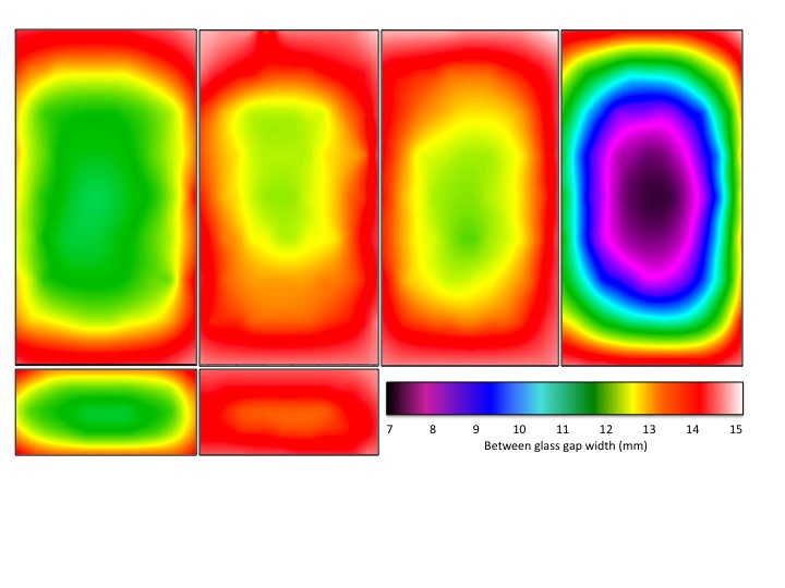
Surface Mapping
The COG gaps of selected units from Site A were mapped as previously noted. Figure 3 shows the deflection shapes of these six fixed- and movable-sash IGUs, four of which measured 1220 mm x 815 mm and two of which measured 455 mm x 815 mm. Maximum deflection occurs at or near the center of all units, and, in general, the deflection shapes follow a similar pattern regardless of the degree deflected, frame configuration, or unit size. Based on these results, we took the COG spot measurements at the center of the interior glazing surface for all remaining units. This is assumed to be the point of maximum deflection.
In all the mapped units, there is a trend of greater deflection at the EOG along the greatest unit dimension. The bias of greater deflection on the left side seen in most units was introduced by our measurement method and the laser alignment of our equipment. Based on the deflection shapes, we made the remaining EOG spot measurements with the plane of the laser parallel to the frame. The recorded measurement was an average of measurements taken at 2 to 4 locations around the perimeter of the unit, to account for variations along the perimeter.
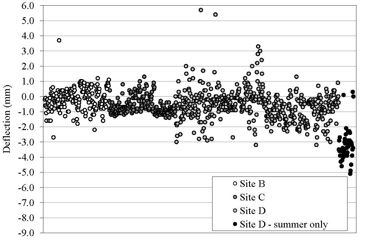
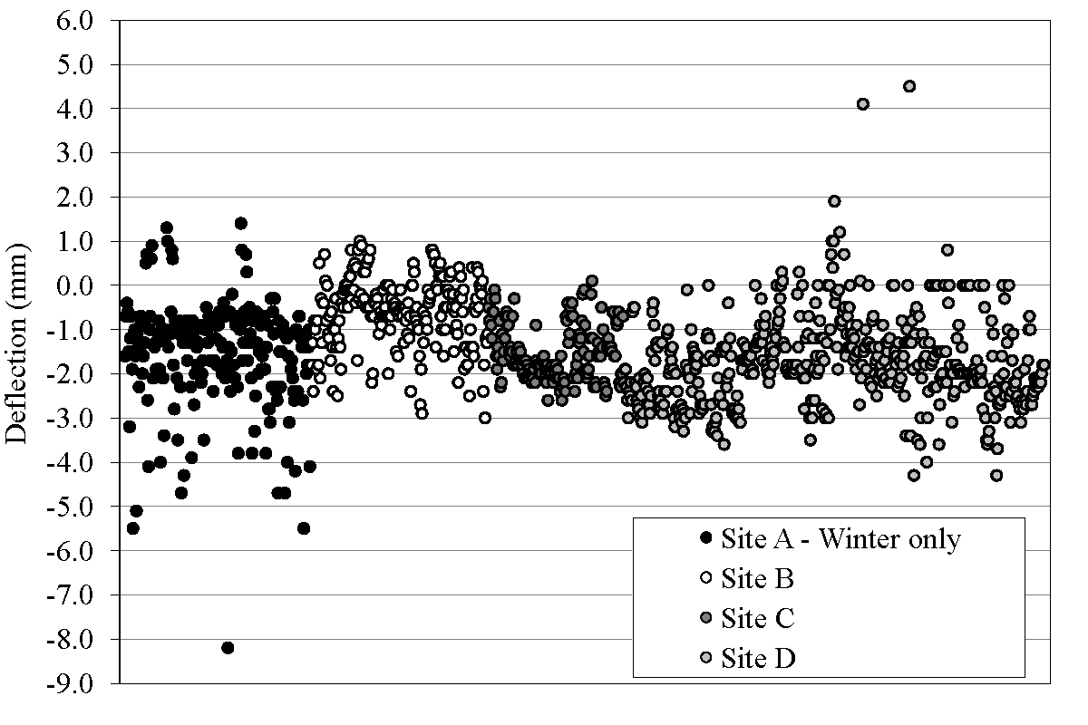
Total Deflection
Figures 4a and 4b show COG deflection for the 1807 total measurements made in this study. The data shown represent all measured windows and include instances of failed IGUs and units in direct sun. Units from Site A were measured in winter only, and one house from Site D was measured in summer only, as indicated in the figures. The difference between the mean winter deflection and mean summer deflections was 0.80 mm. The mean deflection for the measurements is different from the mean absolute value deflection since there are both positive and negative deflections. This explains the small mean deflection with a large standard deviation in the summer measurements. The average indoor temperature rose by 4.8°C from winter to summer; the average outdoor temperature difference was much greater, 21°C from winter to summer. Table 3 summarizes measured deflection and environmental temperatures.
| Deflection | Outdoor Temperature | Indoor Temperature | ||||||||
|---|---|---|---|---|---|---|---|---|---|---|
| Mean (mm) | St. Dev. (mm) | Min (mm) | Max (mm) | Mean (°C) | Min (°C) | Max (°C) | Mean (°C) | Min (°C) | Max (°C) | |
| Winter | -1.43 | 1.09 | -8.2 | 4.5 | 5.3 | -3.3 | 16.4 | 19.2 | 13.0 | 29.0 |
| Summer | -0.63 | 1.13 | -5.1 | 5.7 | 26.3 | 20.1 | 30.0 | 24.0 | 20.6 | 27.7 |
U-Factor Analysis
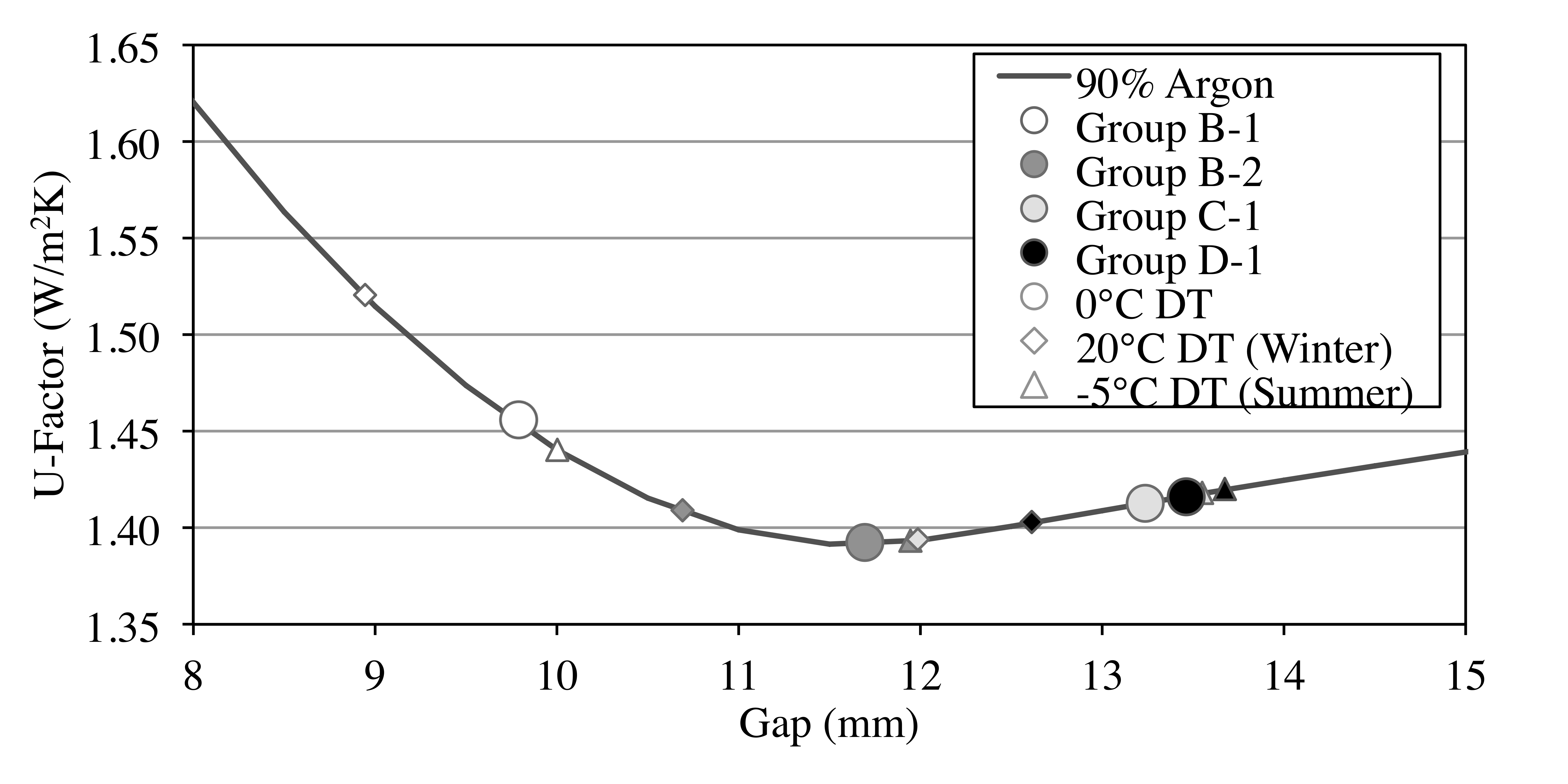
At low Nusselt numbers (Nu) and small deflections a representative average gap width may be reasonably assumed, although large deflections or temperature differences between glass plates will influence convective flow and may make this assumption invalid. The U-factors presented in the following analysis are calculated using Lawrence Berkeley National Laboratory's WINDOW 6 software program, and are based on the average of the COG and EOG mean gap widths, as presented by Bernier [6]. To represent a typical configuration, 3 mm clear glass was used in all models with a spectrally selective low-e coating of emissivity 0.04 on surface 3 of double pane units and surface's 2 and 5 of triple pane units. Gas fill was modeled per the design for each group, as provided in Table 1. All insulated glass units were assumed to be 1000 mm x 1000 mm with a vertical orientation. Even though the environmental temperature differences and wind speed associated with the data are not the ASHRAE type winter test conditions, U-factor modeling was performed at NFRC standard winter environmental conditions, for consistency with U.S. standards [8]. It is worth noting that this is a "generous" estimate of the actual winter test condition performance because all of the measured windows would have even smaller gaps at the ASHRAE-specified winter temperature of -18°C, and the U-factor would increase. The U-factor SE is calculated based on the difference in U-factor from the mean at the gap width of a given DT +/- the gap width SE. This procedure gives approximate values for the mean and standard error. We use it in preference to the standard procedure in that it more appropriately displays the asymmetry in the standard error that arises from the non-linear relationship between U-factor and gap width.
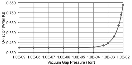
The gap between glass panes is dominated by conduction at gap widths below 4-5 mm, after which the onset of convection occurs. At gap width greater than 4-5 mm the heat transfer rate decreases steadily then levels off at approximately 11 mm for Argon (13 mm for Air and 9 mm for Krypton) at which point boundary layer dominated convection starts. Boundary layer convection creates an isothermal core in the middle of the cavity, making further increases in gap width essentially inconsequential to overall heat transfer.
Summary and Conclusions
Outdoor temperature variations can be represented by a linear change in the COG gap width of double and triple-pane IGUs for the summer to winter temperature ranges measured. The degree of deflection observed varied with the location, configuration, and test conditions for the units studied and could also be attributed to several other unmeasured and unknown effects.
The temperature-induced deflection observed from winter to summer is of similar magnitude to the observed spread of deflection among similar units all exposed to the same temperature in winter and in summer. This was true for windows from several different manufacturers and installation locations, which suggests that there are other factors of equal importance to temperature that determine in-situ deflection of windows.
The impact of deflection on thermal performance is based on the designed gap of the IGU. Units designed with smaller-than-optimal gaps may have significant U-factor changes associated with inherent gap variability compounded with temperature-induced gap reduction. This is particularly problematic for high-performance triple glazing where small gap dimension changes can have a large impact on performance. It is possible to design an IGU with a gap wide enough to mitigate any deflection effects on performance.
Simulation of the thermal impact from COG deflection is included in the WINDOW 7 software from LBNL.
Future Work
Field measurements clearly show a correlation between gap width deflection and temperature, but it is difficult to draw any definitive conclusions from our data regarding the correlation because this study was performed in uncontrolled indoor and outdoor conditions. In addition, it is not possible to isolate correlations with specific window physical properties because of the limited variation in properties among the test units. The next step should be to perform COG measurements under controlled laboratory conditions to quantify deflection shapes and sizes. Mathematical model verification should be performed in parallel with laboratory testing. Deflection calculations based on research from Texas Tech University [5] and U-factor calculations based on computational fluid dynamics/finite element analysis should be compared to the calculation methods used in this study as well as laboratory and field test results.
Relevant Publications
Hart, Robert, Howdy Goudey, Dariush K. Arasteh, and Dragan C. Curcija. "Thermal Performance Impacts of Center-of-Glass Deflections in Installed Insulating Glazing Units." Energy and Buildings 54, no. November 2012 (2012): 453-460.
Facilities
Quantitative IR Thermography
Field Measurements
Introduction
The most insulating glazing units currently have U-factors as low as 0.3-0.5 Watts per square meter Kelvin (W/(m2 K)) and typically employ three glass layers, two or more low-emissivity (low-e) coatings, and an inert gas fill. The most insulating window frames have U-factors as low as 0.6 - 0.8 W/(m2 K) and typically employ low thermal conductivity materials within, or part of, the structural frame. Previous simulation studies analyzing the effects of frame and spacer surface emissivity and conductivity defined research targets for window frame components that will result in better frame thermal performance than is exhibited by the best products available on the market today (Gustavsen et al. 2011). This work expands on the previous research by describing simulation studies analyzing thermal bridging effects of non-continuous operating (and non-operating) hardware in common casement style window frame designs. We use finite volume computational fluid dynamics (CFD) modeling to demonstrate the change in sill U-factor for configurations using typical hardware systems. The thermal effects of hardware are currently ignored in the relatively low performing double pane windows common today, but may become significant in high performance windows.
Window Frames
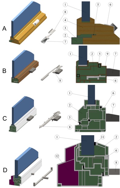
We performed thermal performance simulations on four different window frames: One aluminum clad wood frame (Frame A), one fiberglass (Frame B), and two polyvinyl chloride (PVC) frames (Frames C and D). All the frames were of the outward-opening casement type except Frame D, which was inward opening.
The most significant hardware penetration in each frame is at the sill, therefore the sill frame cross-section is the focus of this work. The modeled sill length of 610 mm the hardware case reflects National Fenestration Rating Council (NFRC) 100 requirements. Three-dimensional frame slices 25.4 mm wide were modeled without hardware to determine the base (reference) performance. Since there are no three-dimensional effects, these models are equivalent to two-dimensional modeling.
The simulated models are simplified representations of common industry frames. Simplification significantly reduces computing time and improves numerical accuracy in the three-dimensional hardware case, but with the risk of inaccurate representation of the actual frame. To address this, we modeled both the actual design and a simplified version for each frame without hardware and verified that the simulated U-factor of the simplified models were within five percent of models with no simplifications. To aid comparisons between the frames, the conductivity of the glazing systems is held constant.
Conclusions
Some conclusions can be drawn regarding the impacts of operating hardware on the thermal performance based on the individual frames, although few general trends can be observed due to the large design differences between each frame section modeled in this study. It is clear that the hardware used in typical out-opening casement windows may have a significant impact on the overall thermal performance of the frame, as two of the three frame sills modeled show reduced performance greater than 0.05 W/(m2 K). It is also clear that the fastener types, operator location, and other factors related to the method of hardware implementation can significantly impact the effect of hardware on the frame. Greater penetration depth of hardware from the warm side surface to the cold side resulted in reduced thermal performance in three of the four frames modeled (Frames A, C, and D). In Frame B, the increased conduction of the hardware was nearly equalized by reduced convection heat transfer made possible by the hardware placement. Neither the base performance level nor the primary frame material appears to determine the thermal effect of hardware based on those metrics alone.
Future Work
The work presented in this study is the initial phase of a larger investigation to determine if the development of new modeling requirements for existing rating systems is needed to properly account for window hardware. This will include validating new thermal rating methods and introducing new technical procedures for incorporating hardware effects into whole window thermal rating methods.
Based on the results from this initial study, we will perform more detailed sensitivity analysis on frame materials, hardware locations, and hardware penetrations. We will also extend our investigations to the performance impacts for alternative frame profiles, including jambs and heads, and frame types, including vertical and horizontal sliders and patio doors. A sensitivity analysis of full frame thermal performance impacts with the same frames is also planned to determine the impact of hardware when the glazing systems improves without changes to the frame. Experimental validation testing of select products in a guarded hot box to verify performance impacts demonstrated in the modeling is also under consideration.
Relevant Publications
Hart, Robert, Cezary Misiopecki, Dariush K. Arasteh, Arlid Gustavsen, and Bjørn Petter Jelle. "Impacts of Operating Hardware on Window Thermal Performance." In BEST3 Conference. Atlanta, GA, 2012.
Gustavsen, A., S. Grynning, D. Arasteh, B.P. Jelle, and H. Goudey. 2011. "Key Elements of and Materials Performance Targets for Highly Insulating Window Frames." Energy and Buildings, Volume 43(10).
Introduction
Commercial fenestration systems mostly employ aluminum framing because of the aluminum alloy's relatively low cost, high strength, easy manufacturability and long service life. However, aluminum has one serious inherent disadvantage in its high thermal conductivity. This limits the ability of most framed commercial windows and facades to meet current thermal requirements. Traditionally, poor thermal performance and low condensation resistance have plagued aluminum framing. Because of this, over the past 20+ years, the design of aluminum framing has been modified to include thermal breaks of various designs, but the thermal performance, while improved, still remains a major limitation to attaining DOE's performance goals. Commercial builders seek window framing solutions with the cost and strength of aluminum products plus improved thermal efficiency to meet more stringent building codes. Window framing approaches, such as those incorporating pultruded fiberglass and other fiber reinforced polymers, have proven to date to be prohibitively expensive for high market panetration, and they cannot be integrated into existing manufacturing processes.
In this project, we develop a new thermal break technology that allows aluminum framing to have thermal performance comparable or better than wood and PVC, while preserving the inherent structural benefits of the aluminum alloy material. In order to ensure our frame design is practical and easily brought from prototype to market, we have worked closely with major commercial window frame manufacturers.
Background
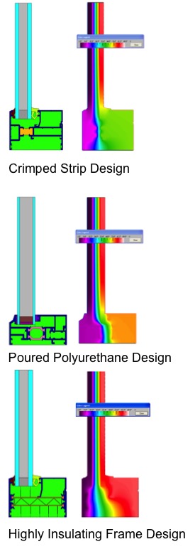
Because of the inherent high conductivity of aluminum framing systems, the designs of Aluminum framing have been modified to include thermal breaks of various designs over the past couple of decades. Technologies used for thermal break are generally divided into two categories, as shown in the figure.
- Pour-and-debridge method, where the framing is extruded as a single piece with the pocket for thermal break. Liquid polyurethane is poured into the pocket and after solidifying, the backing Aluminum section is ground away. This is the older of the two methods, but still in widespread use. The disadvantage of this method is that thermal break width is limited (typically it is about 0.25 in.) by the structural requirements, and the thickness of the thermal break is fairly large, thus limiting the effectiveness of the thermal break. Windows incorporating this type of thermal break have general performance of about U = 0.5 Btu/(hr·ft2·°F), or R2.
- Crimped strips (sometimes called I-bars), where the frame is extruded into two dies and Polyamide strips (usually two) are crimped on each side to create single framing cross-section. Even though Polyamide has higher conductivity than Polyurethane, these strips have smaller cross-section (i.e., thinner) and can have larger widths than pour-and-debrigde systems (normally around 0.50 in.), which allows for better frame performance (typically U = 0.35 to 0.4 Btu/(hr·ft2·°F) or up to R3). Their disadvantage is that this thermal performance cannot be easily be improved further.
Additional, and much less used, methods in use today consist of partial de-bridging of the framing web or steel bolts at regular intervals to fasten indoor and outdoor frame sections. While these methods have improved thermal performance of Aluminum framing, their relatively poor thermal performance still remains an issue and has resulted in relaxed code compliance requirements for commercial framing, as compared to residential framing. Namely, stricter structural requirements for commercial framing have prevented the use wood and PVC framing materials in commercial buildings, which are common materials in residential framing.
Design and Analysis
The goals of our completed frame system are two-fold, first to meet strict structural requirements, and second to meet thermal requirements. Structural requirements are standardized in North America and outlined in the 2011 North American Fenestration Standard/Specification for windows, doors, and skylights (AAMA 101). The outlined fixed window Architectural Window structural requirements include a minimum design pressure of 40 lb/ft2, maximum of L/175 in deflection at design pressure, and life cycle testing, all at a minimum window size of 60 in x 99 in.
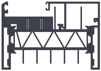
The structural performance of the frame design itself is benchmarked against the performance of current industry frames and to structural criteria using the AAMA technical information report Structural Performance of Composite Thermal Barrier Framing Systems (AAMA 04). The structural calculation procedures outlined in this work are followed for our initial approximations of structural performance. We plan to also follow several industry validation test procedures upon completion of the prototype frame.
While there are no standard commercial frame profile dimensions, the width, 3.25 in., and height (sightline), 2.25 in., overall dimensions of our frame are based on typical sizes found in industry. The frame is designed to accommodate up to a 1.50 in. glazing package with the appropriate glazing bead, but is initially built with a glazing bead to accommodate a more common 1 in. glazing.
Thermal requirements are not as well defined. For commercial and residential applications, windows are typically designed to meet the requirements of the International Energy Conservation Code (IECC), the most commonly adopted model energy code in the U.S. for buildings. Commercial applications often use the ASHRAE 90.1 standard to meet performance or prescriptive based whole building energy requirements. The prescriptive path limits window to wall ratio to 40%, in part to account for the typically low thermal performance of commercial glazing and framing systems.
Glazing systems modeled in a NFRC size fixed window (47 in x 59 in) with three frame types (standard aluminum, traditional thermal break, and the highly insulating frame) show that the traditional thermal break frame ranges from a 40% to 90% improvement over traditional aluminum, and the highly insulating frame achieves a 20% to 90% further improvement over the traditional thermal break frame (80% to 170% over the aluminum frame).
Future Work
Continued development of the frame design is currently being supported with funding from California Energy Commision. Under this funding we plan to complete development of a prototye and perform validation testing.
Introduction
Typical multiple layered windows require a non-reacting, low-thermal-conductivity gas in the space between the glass layers. While argon is used at present in nearly all IGU's, a better choice thermally is (expensive) krypton, which is currently separated from dry, CO2-free air, by high-energy-consuming cryogenic distillation. This process has high operating costs and requires large volumes of material to process to achieve competitive economies of scale. A potential alternate process is separating krypton from dry, CO2-free air by absorption into an ionic liquid at ambient temperature. By comparison, the absorption process uses an ionic liquid that is preferentially selective to the inert gases relative to oxygen and will have lower operating costs and can be scaled to operate economically within smaller oxygen plant capacities, reducing the transportation and handling costs for intermediate oxygen stream. Preliminary analysis and testing indicate that selected nonvolatile ionic liquids exhibit good selectivity for krypton relative to oxygen and nitrogen, substantially above that of common volatile absorption solvents.
Highly insulating triple pane windows have been in the US market for many years but have historically seen limited penetration due to the significant added costs of three glass layers, added gas fill cost, additional low-e coating, bulkier frames, and specialized hardware to handle heavy sashes. For suspended film triple glazing windows, there is no added weight, but the production of suspended film units tend to be labor and energy intensive, resulting in comparable cost increase.
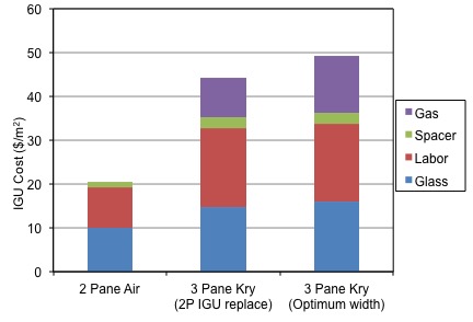
These added costs prevent most homeowners from realizing an acceptable payback for their investment. Recent innovations in low-e coating technology, triple pane assembly line processes, and frame designs have brought these costs much lower though, and krypton is left as the high cost component of the system. To illustrate the significant added cost which krypton adds to IGU's, Figure 4 shows the manufacturer's cost breakdown of three IGU configurations. Krypton currently comprises approximately 25% of the total IGU cost when added to an IGU.
Applications and Markets
Krypton is currently ~100x more expensive than argon, which is prohibitively expensive for widespread market adoption. For the same reasons, xenon is an even better choice thermally than krypton but is another ~100x more expensive than krypton. Kr and Xe are also used for lighting, and electronics (a fast growing market). Unlike other industrial gases, rare-gases are global commodities and supplies are not always based on local production. The gap between worldwide supply and demand usually determines price.
The world production of crude Kr/Xe is controlled by the three largest industrial gas companies with 80% market share: Air Liquide, Praxair, and Linde—plus Iceblick, an East European based company and the second largest global supplier of purified Kr/Xe. The current world production of gas mixture (approximately 90 % Kr, 8 % Xe, and 2% impurities) is around 111 million normal liters. USA produces 12 to 14 Million L of Kr/ Xe with Praxair having about 80 % market share.
Currently, krypton and xenon are produced from cryogenic distillation of liquefied air using different methods depending upon the quantities of Kr and Xe. In the large and conventional air distillation double-column unit, an O2 stream containing highest concentration of Kr (and Xe) is sent to a separate column to produce a crude Kr-Xe mixture that usually contains about 5000 ppm Kr/Xe. This crude mixture is in liquid state. Although it is technically possible to enrich this stream of O2 in Kr/ Xe, the concentration of methane and other hydrocarbons in this mixture becomes higher than 3000-3500 ppm posing a safety risk. The removal of these hydrocarbons from crude Kr-Xe mixture is the next step. This will require the following processing:
- vaporize the crude;
- raise the temperature above 300 °C;
- catalytically oxidize the hydrocarbons to convert them to CO2 and H2O;
- cool to ambient temperature;
- remove CO2 and H2O either using absorption, adsorption, or any other technique.
After the removal of CH4 and other hydrocarbons, the stream is liquefied and cryogenically distilled to produce purity products. The buildup of hydrocarbons and their removal requires intensive downstream processing. This makes the process very expensive. Our process does not require separate removal of hydrocarbons from the feed and may not pose a safety threat. (Statistics are taken from March 2011 — CryoGas International pp 40-43).
Energy Exchange
Energy recovery ventilation is the process of exchanging the energy contained in normally exhausted building or space air and using it to treat, or "precondition" the incoming outdoor ventilation air in residential and commercial heating, ventilating and air conditioning (HVAC) systems. During the warmer seasons, the system pre-cools and dehumidifies while humidifying and pre-heating in the cooler seasons.
The benefit of using energy recovery is the ability to meet the ASHRAE ventilation and energy standards, while improving indoor air quality and reducing total HVAC equipment capacity.
This technology not only demonstrates an effective means of reducing energy cost and heating and cooling loads, but has allowed for the scaling down of equipment. Additionally, this system will allow for the indoor environment to maintain a relative humidity of 40% to 50%. This range can be maintained under essentially all conditions. The only energy penalty is the power needed for the blower to overcome the pressure drop in the system.
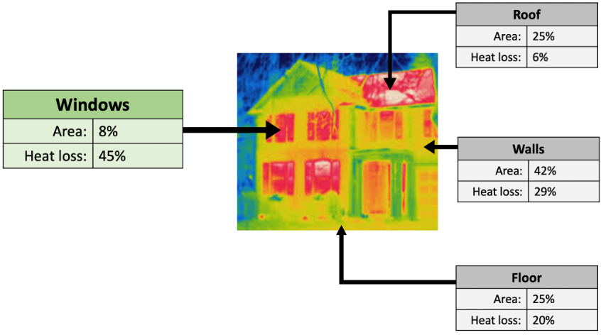
Heat transfer and air leakage through the building envelope comprise the largest HVAC loads in most climates, and windows, which are known as the weakest link in the thermal envelopes, are attributable for approximately 10% of building energy use (Hart et al. 2019).
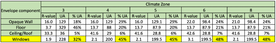
The IECC envelope and air-sealing requirements are designated for eight different climate zones (CZ) in the U.S. Over the past decade, as residential building energy codes have become more stringent, homebuilders have had to adopt new approaches to constructing single-family homes in order to meet these tighter envelope requirements. For example, when wood frame wall insulation requirements were increased to R-20 (in the 2009 IECC for CZ 5-8 and the 2012 IECC for CZ 3-4), wall construction with 2x6 wall studs was required to accommodate the additional cavity insulation. In subsequent versions of the code, options were added to use rigid foam insulation in place of (or in addition to) cavity insulation. Other insulation requirements for ceilings and floors have also steadily increased; the 2021 IECC ceiling R-value requirements are now R-60 for CZ 4-8 (see Table 1).
There are two types of compliance paths to meet the IECC code: a prescriptive path and performance-based paths. Some trade-offs between envelope components (e.g., wall, ceiling, or floor insulation and window performance) are acceptable within the prescriptive path. A simple envelope component tradeoff is allowed based on the overall U-factor times Area (i.e., the heat loss/gain rate) for all components of the envelope, referred to as the “UA” tradeoff approach. For example, one can trade decreased wall efficiency (lower R-value, higher U-factor) for increased window efficiency (lower U-factor). Additionally, the same type of envelope component trade-offs, as well as air tightness, can be made within performance-based paths. The traditional performance path requires that the building as a whole performs to a certain standard and have lower annual energy cost than the same building built to a prescriptive code.
As envelope insulation requirements are raised, the disparity between opaque envelope and window thermal performance becomes more pronounced. For example, in CZ 5 the R-value ceiling insulation requirement has increased from R-38 to R-60 during the past five code cycles while the equivalent window requirements have increased only modestly from R-2.86 (U-0.35) to R-3.33 (U-0.30). This relative disparity in thermal performance draws down the total R-value for the wall assembly. When a homebuilder upgrades the windows of a home from double- to triple-pane, the window performance can improve by 60% or more (U-.30 to U-.19). This added performance can boost the total wall R-value and ensure code compliance while improving thermal comfort. Within the energy code frameworks, the use of higher performance windows allows for some flexibility in envelope construction approaches as well as tradeoffs with other insulating measures. A simple UA analysis of the 2021 IECC requirements show that windows contribute to envelope heat losses at a rate significantly greater than their area fraction would initially indicate, up to 45% of the envelope heat loss on climate zones 4 and 5 despite only representing about 8% of the envelope area.
Builders make wall insulation selections based on a variety of factors including regional preferences, construction practices, and material and labor availability. While the added cost of exterior foam board might be acceptable for a given project, the builder might find the potential moisture control issues and constructability challenges with extended sills and flashing details unacceptable for their project. These builders might see window upgrades as a welcome alternative to adding foam insulation. Alternately, there may be other builders in certain regions and markets who are okay with foam board insulation but would prefer to avoid moving from 2x4 to 2x6 wall stud construction for cost and labor reasons, along with concerns of losing interior floor area.
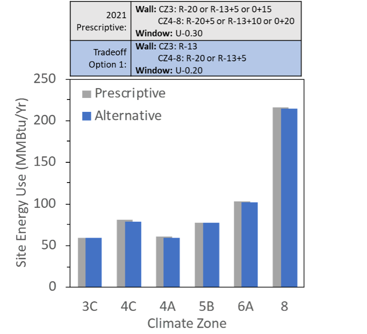
Whole-house site energy use comparison between the model home built to the 2021 IECC prescriptive envelope requirements versus a home built with high-R windows (U-0.20 and SHGC appropriate for climate zone) and 2x4 R13 wall insulation in CZ3 and 2x6 R20 in CZ4-8. These comparisons are presented in terms of site energy savings (MMBtu/Yr.). The results demonstrate that the stud and cavity insulation upgrade in CZ3 and the +5 exterior insulated sheathing in CZ4-8 could be traded off for high-R windows in all climate zones. In CZs 4-8, for example, 2021 IECC requires R-20+5 or R-13+10 or 0+20. For builders who typically build to R-20, the high-R window tradeoff eliminates the need for exterior insulated sheathing (+5), which reduces material costs for the fasteners, sill extenders, and flashing as well as the insulation for these builders. This also means for builders in CZ 3 who prefer 2x4 wall construction without exterior insulated sheathing, the high-R windows tradeoff allows the builder to continue with their desired wall configuration without the need for +5 continuous insulation. These tradeoffs would also allow some flexibility to reduce the amount of exterior insulation below the +10 requirement for builders who prefer 2x4 wall construction in CZs 4-8. These tradeoffs would be allowable under the UA tradeoff approach (e.g., prescriptive path) or through either of the performance compliance paths.
Windows versus Walls
Non-Energy Benefits. In addition to saving energy, the thermal components of a home’s envelope affect occupant comfort, both in terms of temperature and acoustics. In this regard, the added performance of high-R windows is viewed favorably in terms of providing noticeable added comfort to the occupant. Because the current code leaves the window as the relative “hole in the wall” in terms of thermal performance, the act of nearly doubling that R-value by upgrading from double- to triple-panes adds noticeable thermal and acoustic comfort improvement to the home. With higher performance windows, you can increase the home’s window area, for more daylight and views to the outdoors, without sacrificing comfort. From the builder perspective, these are all tangible selling points. In addition, builders have noted that higher performance windows enable them to use shorter HVAC duct runs and interior duct throws as well as downsize HVAC equipment (Gilbride et al. 2019), which provides builders more flexibility in design and additional options to reduce costs.
References
Gilbride TL, S Selkowitz, OG Dingus, and KA Cort. 2019. Double or Triple? Factors Influencing the Window Purchasing decisions of High-Performance Builders. PNNL-28809, Pacific Northwest National Laboratory, Richland, Washington.
Hart Robert, S. Selkowitz, and C. Curcija. 2019. Thermal performance and potential annual energy impact of retrofit thin-glass triple-pane glazing in US residential buildings. Build Simulation 12: 79–86.
Hart, R., S. Selkowitz, M. LaFrance, K. Cort, M. Shirakh, and J. Jennings. “Innovative Market Pathways to Promote Adoption of High-Performance Insulating Windows.” In ACEEE Summer Study Proceedings, August 17, 2020.
It is important that window upgrades are carefully taken into account during retrofit design and HVAC sizing. Often only windows that meet the building code are considered. In addition, window properties are only specified by two numbers: U-value and SHGC. The detailed information below for a wide variety of realistic windows that meeting and exceed code requirements can be used for designers and engineers to design an optimal balance between HVAC components, such as heat pumps, and windows.
Using WINDOW and THERM, the thermal and optical properties of specific window constructions will be added over time to this webpage, which can be used for HVAC sizing calculations.
The first list of windows (PDF) is for Aluminum frame, fixed operator type windows, with glazing systems ranging from single clear and tinted, double clear and high/medium/low solar gain, and triple clear and high/medium/low solar gain, each with either Air or Argon gap fills.
The PDF linked above also has a link to a zip file containing two Energy Plus IDF files for each specific window in the list. There is an IDF file with average spectral data for the glass (AVG) and one with detailed spectral data for the glass (SPEC). The IDF files can be included in an Energy Plus simulation for much more accurate modeling of the windows.