Facilities
Facilities
The Windows Group has facilities for measurement of window elements on scales ranging from full test beds for annual testing to lab instruments for analysis of the thermal and optical properties of individual elements of the products being studied.
Solar Optical Properties Laboratory
- Transmittance and reflectance in the solar wavelength range
- Goniometers for angle-resolved scattering
- Thermal IR reflectance of low emissivity materials
Ellipsometry is a powerful tool for determining the optical indices and thicknesses of the layers in a thin-film coating especially when combined with radiometric data from our other instruments. This information is used both for analysis of our coating structures and to develop models for optical properties of various solar energy materials.
 The JA Woollam VASE ellipsometer is a commercial ellipsometer that measures the change in polarization as light is reflected from the surface of the studied sample. The method is standard for obtaining optical constants (n, k) as well as thickness for thin film coatings on glass.
This ellipsometer can also be used in "scatterometer mode" in which it acts as a spetrophotometer with in-plane bidirectional goniometer function. The ellipsometer shown below by the J.A. Woollam Co. covers the ultraviolet, visible and near infrared range from 250-1700 nm.
Attributes and Capabilities
- Wavelength range 300-1700 nm
- Sample size 2x2” to 3x3” is ideal, larger or smaller samples can be accommodated using special procedures.
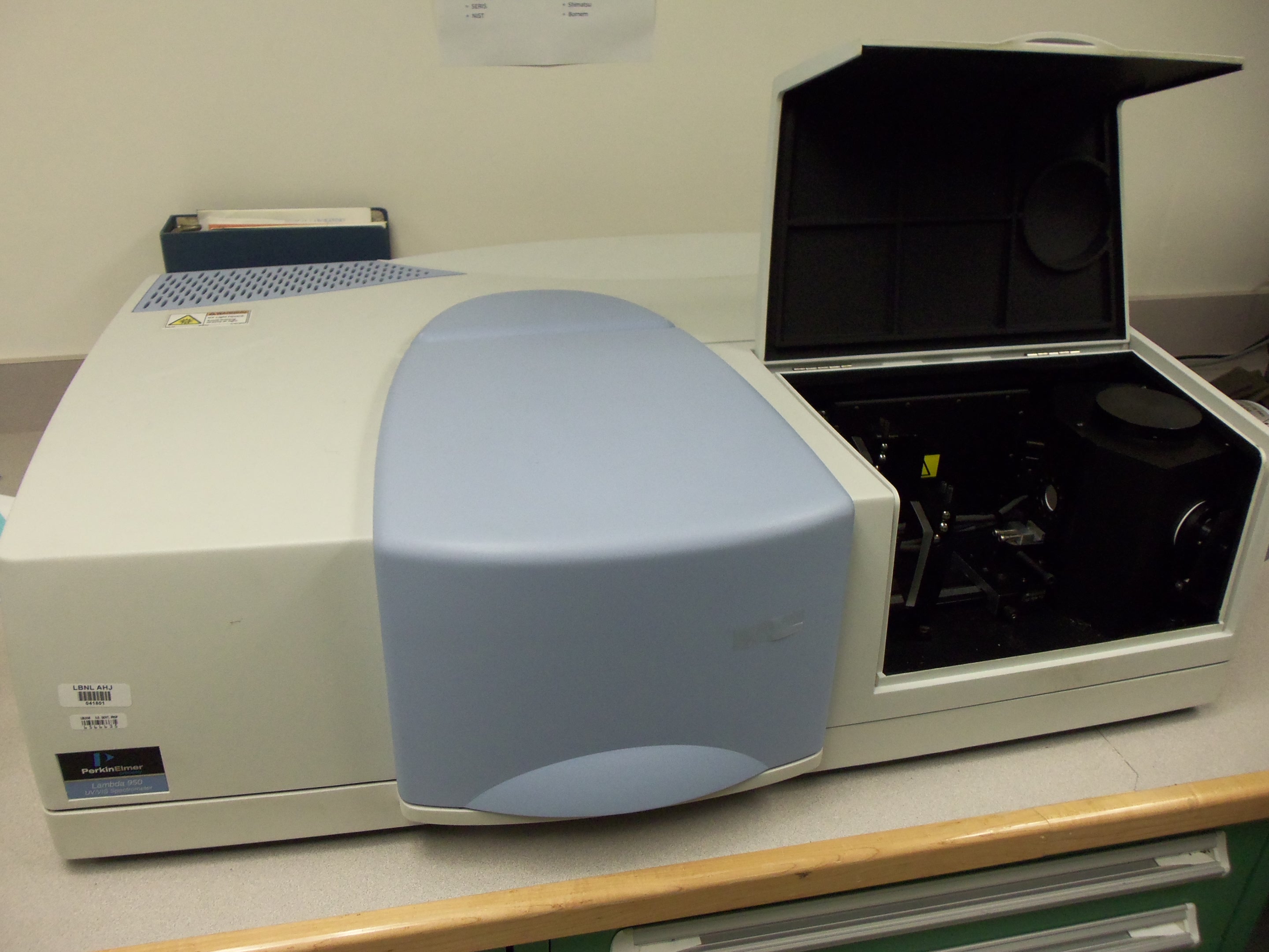
Lambda 950 with 150 mm sphere
Measurements of solar spectral transmittance and reflectance as a function of wavelength are made with a scanning spectrophotometer. Our older UV-VIS-NIR spectrophotometer is the Perkin-Elmer Lambda 950 fitted with an 150 mm integrating sphere. The main light source is a tungsten halogen lamp which is complemented by a Deuterium lamp for shorter wavelengths. Near infrared wavelengths are detected using a PbS detector and a photomultiplier tube cover wavelengths shorter 860 nm.
This is a standard style of instrument for measurement of data that is submitted to the IGDB (international glazing database).
In addition to measurement of reflectance and transmittance the instrument can also be used to obtain haze values according to ASTM D1003.
Attributes and Capabilities
- Wavelength range with integrating sphere 300-2500 nm, specular accessory 200-3300 nm, shorter wavelengths possible if purged with N2.
- Sample size 2x2" to 3x3" is ideal, larger or smaller samples can be accommodated using special procedures.
- Calibrated second surface reference mirror from OMT solutions for high precision reflectance measurements.
- Custom mounted rail for measurement of the bi-directional transmittance distribution function (BTDF), procedure developed at LBNL described in "Obtaining the bidirectional transmittance distribution function of isotropically scattering materials using an integrating sphere", Jacob C. Jonsson and Henrik Brandén, Optics Communications, 277, 228-236 (2007)
- Set of angle tubes for measurements at varying angles of incidence at 5 degree increments, described in "Determining Off-Normal Solar Optical Properties of Drapery Fabrics", Nathan Kotey, John L. Wright, and Michael Collins, ASHRAE Transactions, 115, (2009)
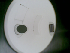
Angle tube with green shade material inserted into the integrating sphere
75 degrees is the largest angle of incidence, the sample is wedged using a sleeve system.
We developed a heating frame to measure thermochromic samples in 2013, documented in DOI: 10.1520/JTE20120341. In 2021 we built a heating cell to increase the flexibility of sample dimensions as well as removing the temperature gradient over the sample.
The yellow rectangle marks the area of the sample that
is illuminated by the light beam.


Lambda 1050 with 270 mm sphere
Measurements of solar spectral transmittance and reflectance as a function of wavelength are made with a scanning spectrophotometer. Our most modern UV-VIS-NIR
spectrophotometer is the Perkin-Elmer Lambda 1050 fitted with a 270 mm integrating sphere. The main light source is a tungsten halogen lamp which is complemented by a Deuterium lamp for shorter wavelengths. Near infrared wavelengths are detected using a InGaAs detector and a photomultiplier tube cover wavelengths shorter than 860 nm.
The larger integrating sphere meets the requirements of NFRC 300 for measurement of diffuse glazing.
Attributes and Capabilities
- Wavelength range with 270 mm integrating sphere 300-2500 nm.
- Apperture matching NFRC 300 diffuse glazing requirements is 100 mm diameter.
- Sample size 4x4" to 5x5" is ideal, larger or smaller samples can be accommodated using special procedures.
- Calibrated second surface reference mirror from OMT solutions for high precision reflectance measurements.
Projects Using These Instruments
- Characterization of light-scattering glass like fritted glass and diffuse interlayers.
- IGDB interlaboratory comparison. LBNL conducts a parallel (every lab gets a set of samples) ILC every four years to verify that their measurements are withing expected range and does not contain systematic errors.
- Characterization of fabrics used in different window attachments both at normal and oblique angles of incidence.
- Characterization of haze for diffuse materials.
- Development of a method to obtain BTDF data by positioning the sample at different positions from the entrance port.
Note: For fast measurements of IR emissivity we have a Devices and Services AE1 RD1 emissometer.
Operation
It warms up time in 30minutes after which each measurement takes 90 seconds or less.
At the start of the measurement session the instrument is calibrated using a high (0.88) and low (0.05) reference sample.
To avoid inaccuracy from instrument drift the reference samples should be checked frequently.
If the sample is transparent in the IR range it is possible to obtain both emissivity and transmittance by measure using a dark and light background backing.
Results
The data produced by this instrument is a single number of the hemispherical IR emissivity, i.e. the value that is used in most thermal calculations.
Examples of Use
- The AE1 RD1 has been used to measure the emissivity of a wide range of aluminum frame materials.
- Emissivity of low-E coatings have been measured in agreement with FTIR inter-laboratory comparison.
The Perkin-Elmer Frontier FTIR spectrometer measures transmittance and reflectance in the wavelength range from 2.5 to 44 microns. Measures hemispherical thermal emissivity of opaque samples. The instrument is fitted with a PYKE 10 degree angle of incidence reflectance accessory.
Attributes and Capabilities
- Ideal sample size to allow measurements at oblique angles of incidence is 3”x3”.
- After a warm-up time of 30 minutes each measurement takes 5-10 minutes depending on noise level.
- Calibrated using a gold reference mirror

Chart of transmittance and reflectance measurements in the wavelength range of four glass samples.
This instrument was designed and built by pab advanced technologies Ltd to meet our specific needs. Situated in a dark room this version is be able to span the full solar spectrum with high speed, precision and angular resolution for any possible angle of incidence.
Using a tungsten halogene light source and filtered Si-detectors it can obtain data in different wavelength bands. The NIR wavelengths are covered with an InGaAs detector.
Rendering of instrument by Peter Apian-Bennewit shown to the right.
Attributes and Capabilities
- Ideal sample size to allow measurements at oblique angles of incidence is 3”x10”.
- Angle of incidence -80 – 80 degrees
- Silicon and InGaAs detectors combined with filters are used to select wavelength bands to study
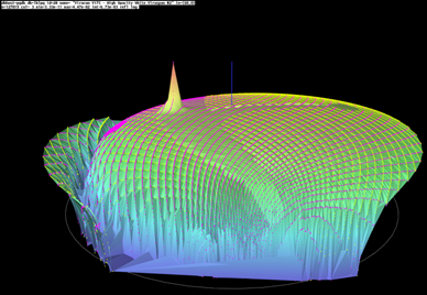
An example how data can be visualized is shown below, this is the reflectance at 60 degrees angle of incidence for a fritted glass sample. This graph show one angle of incidence, a complete BSDF used in WINDOW would typically consist of 145 datasets like this.

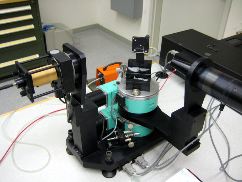
The Optronic Laboratories OL-750 was built to LBNL specifications to measure specular transmittance and reflectance versus angle of incidence for specular samples. The sample can be rotated and translated with 5 degrees of freedom and the detector moves in the horizontal plane of the instrument (not necessarily the scattering plane of the sample) to measure reflectance and transmittance. The freedom of movement of the detector also allows the instrument to be used for angle-resolved scattering measurements.
Operation
The sample can be rotated to vary the angle of incidence as well as lateral positioning of the sample.
The detector moves in the horizontal plane of the instrument and detects the scattered light in that direction for the given incidence angle of the sample.
Either a silicon or a lead sulfide detector is mounted on the detector arm, giving a choice of wavelength from 350-1100 nm or 1100-2500 nm.
Results
The data collected with this instrument can be used to calculate the bi-directional scattering distribution function (BSDF) for the sample.
Examples of Use
Brushed aluminum venetian blind slats has been characterized using this instrument.
Anisotropic samples cannot be fully characterized due to the limited range of motion of the sample holder.
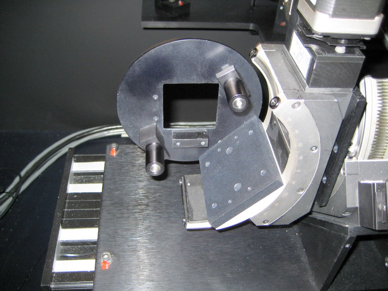
Below is a close-up on the intricate combination of motors that allow 5 degrees of sample movement.
Attributes and Capabilities:
- Wavelength range 300-2500 nm
- Sample holder is limited to samples of size between 2x2” and 3x3”
- Angle of incidence -20 – 80 degrees
- Outgoing angle limited by angle of incidence
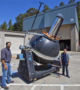
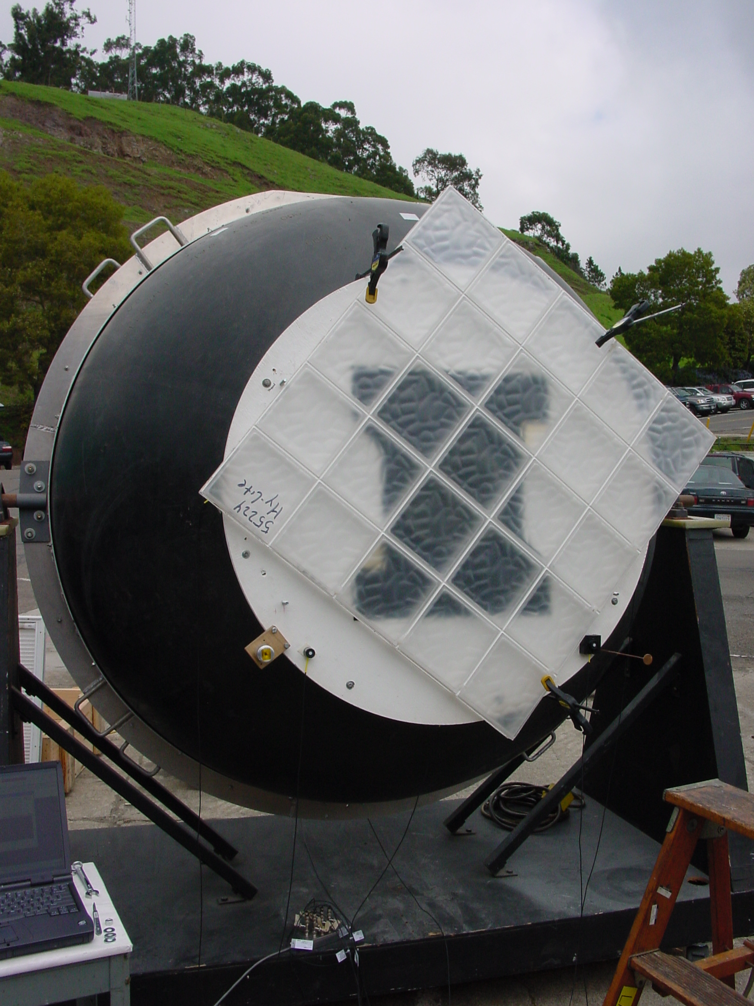
The theory and application of this sphere is described in the following two papers:
- Kessel, Jeffrey. "Transmittance Measurements in the Integrating Sphere." Applied Optics 25 (1986): 2752-2756. [PDF]
- Kessel, Jeffrey, and Stephen E. Selkowitz. "Integrating Sphere Measurements of Directional-Hemispherical Transmittances of Window Systems." In Illuminating Engineering Society Annual Technical Conference. St. Louis, MO, 1984. [PDF]
The integrating sphere has been used to develop measurement standards for characterization of tubular daylighting devices.
Attributes and Capabilities:
- Motorized position relative to the sun allows rapid measurement of many incidence angles
- Validates optical models for light redirecting samples under variable angle of incidence
- Basis for NFRC 203 standard development
Hand-held devices that can be used to inspect glass and windows in the field.
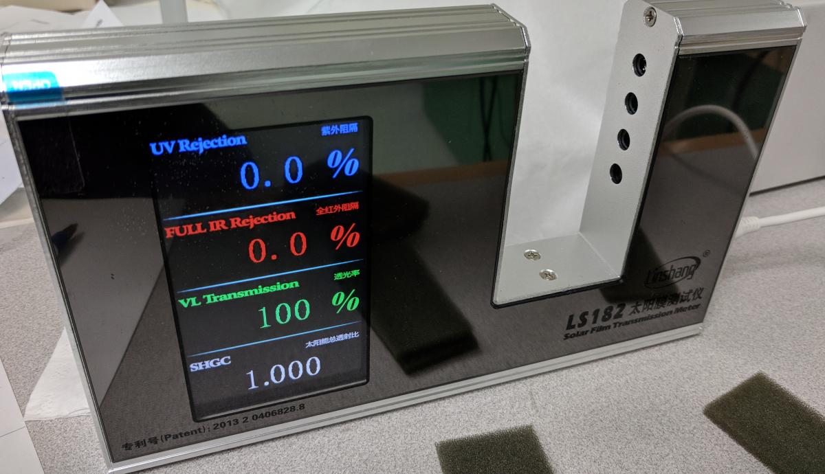
Visible and solar transmittance meter
The LS182 solar transmittance meter promises a bit more than it delivers, but can still be used to provide useful data. Four parallel detectors measure the transmittance of the sample in 4 different wavelength bands. Comparison with full spectrum measurement of three specular sample is presented in a pdf file in the attachment section of this web page.
The large gap between sensor and detector allow for measurement of IGUs as well as single layers.
Experiments with a light-scattering sample indicated that the detector was not able to capture enough of the light to be trustworthy.
Measurement of specular visible transmittance had good agreement, and the agreement on SHGC was fairly sample dependent, with no clear trend.
Thermal Properties Laboratory
Thermal testing facilities at LBNL serve to assure credibility of models and software tools and to determine thermal performance of new products and technologies.
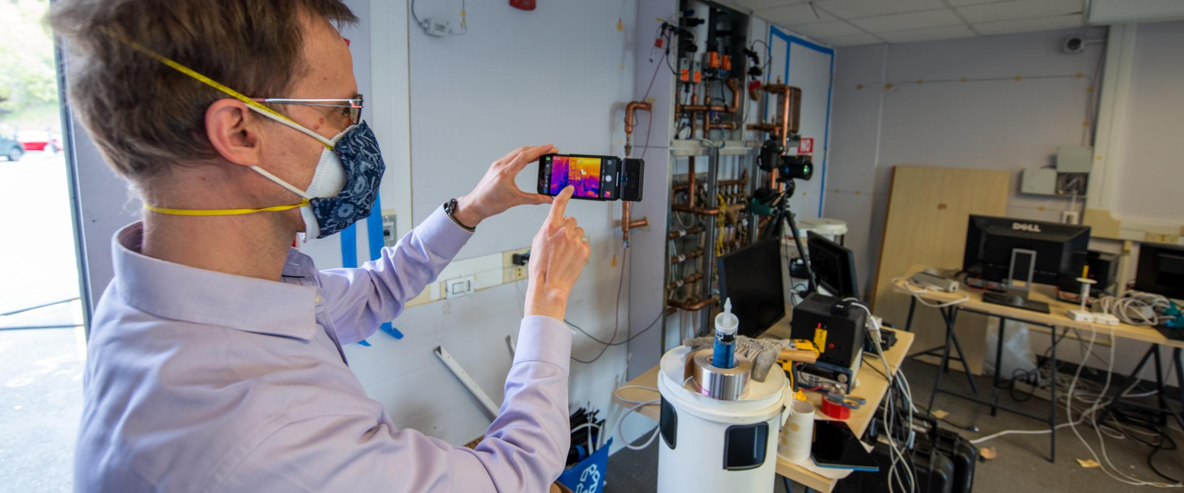
The human eye can't see the heat that shines off of everyday objects. But with the help of infrared imagers, researchers can "see" and measure this heat which radiates from every surface. This data can produce images called thermograms that are based on the temperature of objects. This type of thermal testing has the advantage that large amounts of surface temperature data can be collected without disrupting the test situation. The data are collected as an image that allows for a quick understanding of the relative performance of various parts in the system.
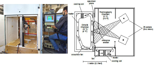
Using environmental chambers similar to commercial window testing calorimeter chambers, the Quantitative Infrared Thermography Laboratory (IRLab) is designed to allow the collection of high resolution quantitative surface temperature data using an infrared camera. Uniform enclosure temperature and air flow conditions, detailed background radiation correction and external referencing for the IR camera, all contribute to achieving quantitative surface temperature with an accuracy of +/-0.5C, comparable to many contact measurement techniques, while providing unmatched spatial resolution of surfaces temperatures.
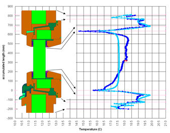
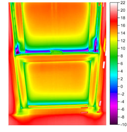
Beyond the visualization of detailed surface temperature patterns revealed in an infrared thermogram image (Figure 1), the surface temperature data are post-processed to extract calibrated and background corrected numerical data that can be compared to computer simulation results for model validation purposes (Figure 2), or provide local performance information when developing high thermal performance prototype products. In addition to surface temperature data collected by the IR camera, a computer controlled 3-axis motion system can position air temperature and velocity sensors in the warm side air space near to the specimen. Figure 3 depicts the open view to the specimen within the warm side environmental chamber necessary for infrared thermography. There is no internal metering box enclosure typical in a calorimeter. A cross-sectional schematic of the configuration of the cold chamber, specimen plane and the warm chamber is also shown in figure 3. Temperature controlled air flow patterns and the two typical views of the infrared camera are also shown in the schematic. The IRLab contains a machine tool fabrication area that supports fabrication of specimens and test apparatus efforts in the Building Technologies Department.
The primary measurement goals of the facility include assessment of the performance of energy-efficient windows currently available or under development, identification of opportunities for new development, and to create a knowledge base that will encourage the rational selection of optimal windows in the design process. In addition to its DOE-supported research, the IRlab is also available for privately-funded studies of specific products or window improvement options. It can:
- provide empirical data for thermal model validation and development
- generate detailed, quantitative, high resolution surface temperature measurements
- identify local thermal bridging (thermal performance non-uniformity)
- operate at a variety of steady state environmental conditions
Thermogram
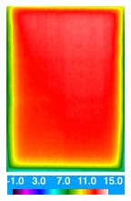
This image is called a thermogram. Each pixel of a thermogram has a temperature value and the image's contrast is derived from differences in surface temperature. The specimen here is a normal dual pane window. Cold air is blowing along the back side. The scale at the bottom shows the relation between temperature and color. Note the cooler conditions around the perimeter of the glass, this is due to high heat flow through the aluminum spacer located between the two panes of glass.
Accomplishments
In recent projects, researchers have analyzed:
Film coefficient and convection problems for the National Fenestration Rating Council
- Vacuum Glazing prototypes produced by the University of Sydney
- Double, triple, and quadruple glazings
- Low conductivity spacers
- Vinyl window frames
- Wood casement windows
- Double-hung windows
- Integrated Window System prototypes produced by LBNL
- Gas-Filled Panel opaque thermal insulation produced by LBNL
Projects
- Vacuum Insulated Glazing (VIG)
- Highly Insulating Windows with Automated Shading
- Triple Glazing with Thin Non-Structural Center Glass
- Center-of-Glass Deflection
The Thermal Properties Laboratory includes a collection of research integrated machine tools to enable rapid fabrication and testing of experimental specimens, as well as development of custom fixtures, sensors and test hardware. Materials worked vary from metals and wood to plastics and foam.
The machine tools include:
- CNC 3-axis vertical milling machine
- Lathe
- Drillpress
- Vertical bandsaw
- Tablesaw
- Chopsaw
- Horizontal bandsaw
- Belt sander
- Grinder
- Router
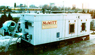
The Mobile Window Thermal Test Facility is dedicated to the evaluation of the thermal performance of window systems by measuring the net energy flow through full-scale sample windows in two side-by-side, room-size outdoor calorimeters. Net energy flow is characterized as a function of ambient conditions, enabling scientists to derive U-factor and solar heat gain coefficient (SHGC) properties of innovative systems. Because the facility is mobile, samples can be exposed to different orientations and climates. Accurate measurements of time-varying heat flows under realistic outdoor conditions also enable scientists to derive and validate numerical models used in simulation software, improving confidence in the specification of new products.
Download a summary of the facility (.pdf).
Projects
Vacuum Insulated Glazing (VIG)
Highly Insulating Windows with Automated Shading
Full-Scale Testbeds
Our test facilities, simulation tools, websites, and guidelines help stakeholders apply this research to the design and development of energy-efficient building façade solutions.

The Mobile Window Thermal Test Facility is dedicated to the evaluation of the thermal performance of window systems by measuring the net energy flow through full-scale sample windows in two side-by-side, room-size outdoor calorimeters. Net energy flow is characterized as a function of ambient conditions, enabling scientists to derive U-factor and solar heat gain coefficient (SHGC) properties of innovative systems. Because the facility is mobile, samples can be exposed to different orientations and climates. Accurate measurements of time-varying heat flows under realistic outdoor conditions also enable scientists to derive and validate numerical models used in simulation software, improving confidence in the specification of new products.
Download a summary of the facility (.pdf).
Projects
Vacuum Insulated Glazing (VIG)
Highly Insulating Windows with Automated Shading

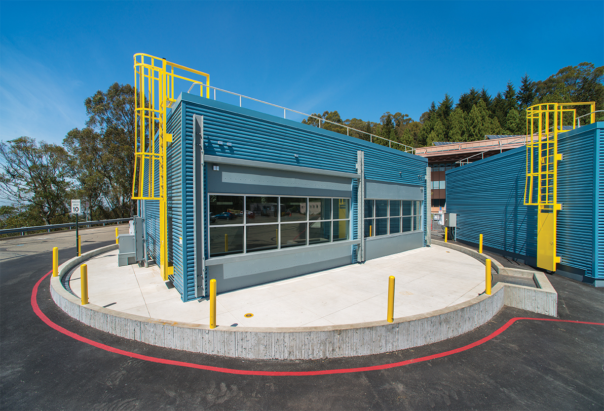
The Advanced Windows Testbed enables investigations of system-level interactions between innovative façade systems and lighting and HVAC systems. Users can conduct outdoor tests in three full-scale, side-by-side instrumented test chambers. Each chamber is thermally isolated so that window heat flow measurements can be made on a comparative basis. The chambers are designed to emulate typical private offices, so that daylighting, comfort, and human factors studies can be conducted as well. Exterior and interior window attachments can be rotated every three to five days using hoist mechanisms, enabling a maximum of eight different test conditions to be evaluated over a solstice-to-solstice period. Scientists collaborate with industry to vet prototype systems; working out control system designs for dynamic, intelligent façade systems or characterizing the luminous environment resulting from innovative daylighting systems. Performance data are used to assess market readiness and quantify energy and non-energy benefits of new technologies prior to commercial release.
Download a summary of the facility. (.pdf)
")
Left image: Dennis DiBartolomeo (foreground) and Kyle Konis changing out a motorized exterior blind outside the Advanced Windows Testbed. Right image: Eleanor Lee, Staff Scientist (left), and Erin McConahey, Arup (right), discussing innovative shading technologies in the Advanced Windows Testbed.
Contact
Projects
Daylight Systems
Intelligent Dynamic Façades
 FLEXLAB®
The Facility for Low Energy EXperiments (FLEXLAB®) is an advanced building simulator designed to save time and money and promote energy-efficiency. FLEXLAB allows businesses, governments and others to test and optimize many systems before the building is built.
The Department of Energy's FLEXLAB® at Berkeley Lab is the most flexible, comprehensive and advanced building efficiency simulator in the world, and is unleashing the full potential of improved energy efficiency in buildings. FLEXLAB lets users test energy-efficient building systems individually or as an integrated system, under real-world conditions.
FLEXLAB test beds can monitor and assess HVAC, lighting, windows, building envelope, control systems, and plug loads, in any combination. Users can test alternatives, perform cost-benefit analyses, and ensure a building will be as efficient as possible — before construction or retrofitting even begins.
FLEXLAB is the latest in Berkeley Lab’s long line of game-changing energy efficiency innovations.
Read more about FLEXLAB at flexlab.lbl.gov