Electrochromic Materials
Electrochromic Materials
How They Work
Electrochromic glazings have great potential to improve the energy efficiency and occupant comfort afforded by architectural windows. These smart windows can dynamically control light transmission by windows in buildings, automobiles, and aircraft. Electrochromic glazings are the most significant members of a family of chromogenic light-control technologies that includes large-area dispersed liquid crystals, dispersed particle windows, and photochromic and thermochromic materials. Electrochromic devices represent the most versatile window technology of this type, exhibiting the best combination of switching properties for chromogenic window applications.
Electrochromic glazings typically have a change in visible light transmission from 10% to 70%, moderately fast switching times, and low dc power consumption. These glazings have memory, so they only need power to make a change in transmission. Electrochromic technology can be coupled with smart control systems to give constant lighting levels, blending artificial lighting with daylighting for improved building energy efficiency. Energy simulations of office buildings, below, indicate that smart windows with lighting controls in arid climates can provide 30-40% energy savings over conventional windows. Savings are realized in cooling, lighting, and peak utility electric loads. Other benefits include smaller heating, ventilating, and air-conditioning (HVAC) systems and greater thermal and visual comfort.
In this section is an image of an LBL electrochromic window, showing the bleached condition, intermediate coloration, and fully colored (top to bottom). The window is constructed of thin films of tungsten oxide and lithium nickel oxide laminated with a polymer ion conductor. The visible transmittance range is Tv = 0.68-0.10 and solar transmittance range is Ts = 0.47-0.07.
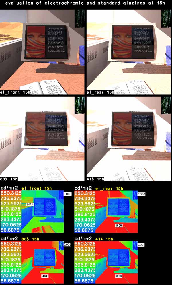
The following simulations show the effects of different glazings on video display terminal glare, etc.

Video Display @ 9:00 am
(122 K)

(115 K)

(96 K)
(107 K)

(128 K)

(128 K)
About the Office Animation
Physical Setup of the Office and Simulation
Download Electrochromic Office Animation
(3.8 MB MPG)
- Office room dimensions: 10 feet wide (N-S) by 20 feet long (E-W)
- Glazing Clear opening dimensions: 10 feet by 5.75 feet
- West facing glazing three floors above street level
- CIE Clear skies with direct sun
- Building located in San Francisco (37.8 N latitude, 122.4 W longitude) in a mid-rise, office/industrial neighborhood
- Electrochromic device time sequence and spectral transmittance and reflectance measurements based 1 foot square prototype Tungsten Oxide (WO3) devices provided by industry-leading glazing manufacturers.
- Dynamic exposure compensation with pcond foveal-weighted averaging applied to each frame
Sequence of Events
- 15:00:00, sun obscured by a cloud, glass at full transmittance: Tvis=74%
- 15:00:03, cloud moves away and direct sun enters the office
- 15:00:12, electrochromic glazing begins to color at its maximum rate
- 15:04:06 through 15:17:42, video is in 10X time lapse to prevent boredom
- 15:17:42, electrochromic glazing reaches its maximum coloration: Tvis=3.2%
- 15:17:48, the cloud moves in front of sun obscuring all direct sun
- 15:17:54, electrochromic glazing begins to bleach at its maximum rate
- 15:22:18, electrochromic glazing reaches its maximum bleached: Tvis=74%
The Electrochromic Glazing Office Animation is created using an image compositing method whereby separate images of the office generated with only one source of illumination are added together in variable percentages to come up with the final image. This method assumes that the sources of illumination do not change position through the animation sequence. Although the sun does move approximately 5 degrees during the span of this 20 minute animation sequence, because this movement is not the focus of the simulation and does not significantly change the intensity of the solar exposure, it is ignored. This method takes advantage of the principal of the scalability of light to avoid the significant time involved in calculating separate Radiance renderings for each combination of sky condition (direct sun versus no direct sun) and electrochromic glazing transmission.
First, an image of the office with only the computer monitor "turned on" and without direct sun and without ambient sky component is rendered. (This results in a very dark room indeed.) Then, an image of the office with only the ambient sky component is rendered. Next, an image of the office with only the direct sun component is rendered. Each of these images is rendered with exactly the same viewing parameters resulting in three images that are perfectly aligned, pixel by pixel. Then, the Radiance pcompos program adds together each pixel of the images according to a function which defines the percentage of each light source which is desired. The desired percentage depends partly upon the measured transmittance of the EC device.
LBNL performed time sequence and spectral measurements of large prototype (one foot square) electrochromic devices provided by leading glazing industry manufacturers. Researchers employed a Lambda 19 spectrophotometer equipped with a BaSO4 coated integrating sphere to obtain the transmittance and front and back reflectance of the EC devices.
In the case of electrochromic glazing, time sequence and spectral measurements of prototype EC devices are plugged into a simple ASCII control file. The control file also includes instructions on how to control the changing sky conditions and what text to overlay on the image. The control file then informs the image composing process such that the impression of changing sky conditions and electrochromic tinting is created. The interior ambient and direct solar lighting conditions change in proportion to the visible transmittance of the electrochromic glazing.
Finally, each composted rendering is then passed through a Radiance pixel filtering program called pcond which first determines an appropriate exposure level for that image and then applyies a dynamic, pixel-by-pixel exposure compensation accordingly. The exposure level is based upon a foveal-weighted luminance map and a luminance histogram of every pixel of the image. The assumption is that the electrochromic glazing is changing slowly enough for the human eye to immediately adapt to the changing lighting levels.
Each frame of the animation sequence is created in this manner, and then sent frame by frame to a Sony laser video disk using the NTSC video output board of the Silicon Graphics Indy workstation and the scry video interface software. Individual VHS tapes are then produced from the video disk master.