Checking Tolerance
Checking Tolerance
Originally Posted:
Friday, January 12, 2024
Last Updated:
Friday, January 12, 2024
Software/Versions Affected:
- THERM›7
See also
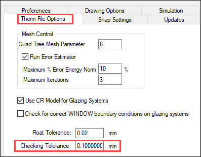
The Checking Tolerance is used to determine if points are too close to each other.
The default value is 0.01 mm.
The ability to control this value was introduced in THERM 7.7 (and is not in THERM 7.4).
The Checking Tolerance values can be set by going to the Options / Preferences menu, and then the Therm File Options tab
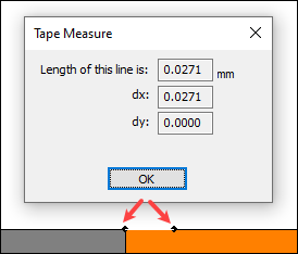
For example, the model below has two points that are 0.0271 mm apart, which is quite close, and would fail the test of being no closer than 0.01 mm.
For this model, when a user presses the BC toolbar icon  , to generate the Boundary Conditions, THERM will check to see if any points are close to each other before proceeding further. With the Checking Tolerance set to 0.01 mm, the program will show the following message:

If the user chooses the 2nd option, "Mark the points but don't adjust them", the program will show a red circle around the points that are too close together.

On option is to delete the second point to the right.
But if the point is an important part of defining the geometry, the user can change the Checking Tolerance to 0.02 mm, and the model will pass the Boundary Condition creation, as now the point distance of 0.0271 mm is greater than 0.02 mm

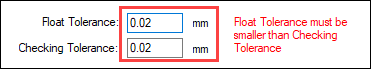
Float Tolerance must be smaller than Checking Tolerance
In order for a model to mesh, it is necessary for the Float Tolerance to be smaller than the Checking Tolerance. THERM will show an error if they are not set properly